Drill tool shaft-to-housing locking device

a technology of locking device and drill bit, which is applied in the direction of drilling pipe, directional drilling, borehole/well accessories, etc., can solve the problems of reduced drilling bit penetration rate, frequent problems, and wear of downhole motors

Inactive Publication Date: 2007-06-26
HALLIBURTON ENERGY SERVICES INC
View PDF45 Cites 40 Cited by
  • Summary
  • Abstract
  • Description
  • Claims
  • Application Information

AI Technical Summary

Benefits of technology

[0048]The deflection actuator is preferably further comprised of a power source for effecting longitudinal movement of the deflection actuator. The power source may be comprised of any structure or apparatus which can effect longitudinal movement of the deflection actuator.
[0049]For example, the power source may be comprised of hydraulic pressure exerted directly on the deflection actuator by drilling fluid being passed through the drilling direction control device. Preferably the power source is comprised of a hydraulic system contain...

Problems solved by technology

However, various problems are often encountered with sliding drilling.
As well, the downhole motor tends to be subject to wear given the traditional, elastomer motor power section.
Furthermore, since the drilling string is not rotated during sliding drilling, it is prone to sticking in the wellbore, particularly as the angle of deflection of the wellbore from the vertical increases, resulting in reduced rates of penetration of the drilling bit.
Other traditional problems related to sliding drilling include stick-slip, whirling, differential sticking and drag problems.
For these reasons, and due to the relatively high cost of sliding drilling, this technique is not typically used in directional drilling except where a change in direction is to be effected.
However, rotary drilling tends to provide relatively limited control over the direction or orientation of the resulting wellbore as compared to sliding drilling, particularly in extended-reach wells.
Although ...

Method used


Image

  • Drill tool shaft-to-housing locking device
  • Drill tool shaft-to-housing locking device
  • Drill tool shaft-to-housing locking device

Examples


first embodiment

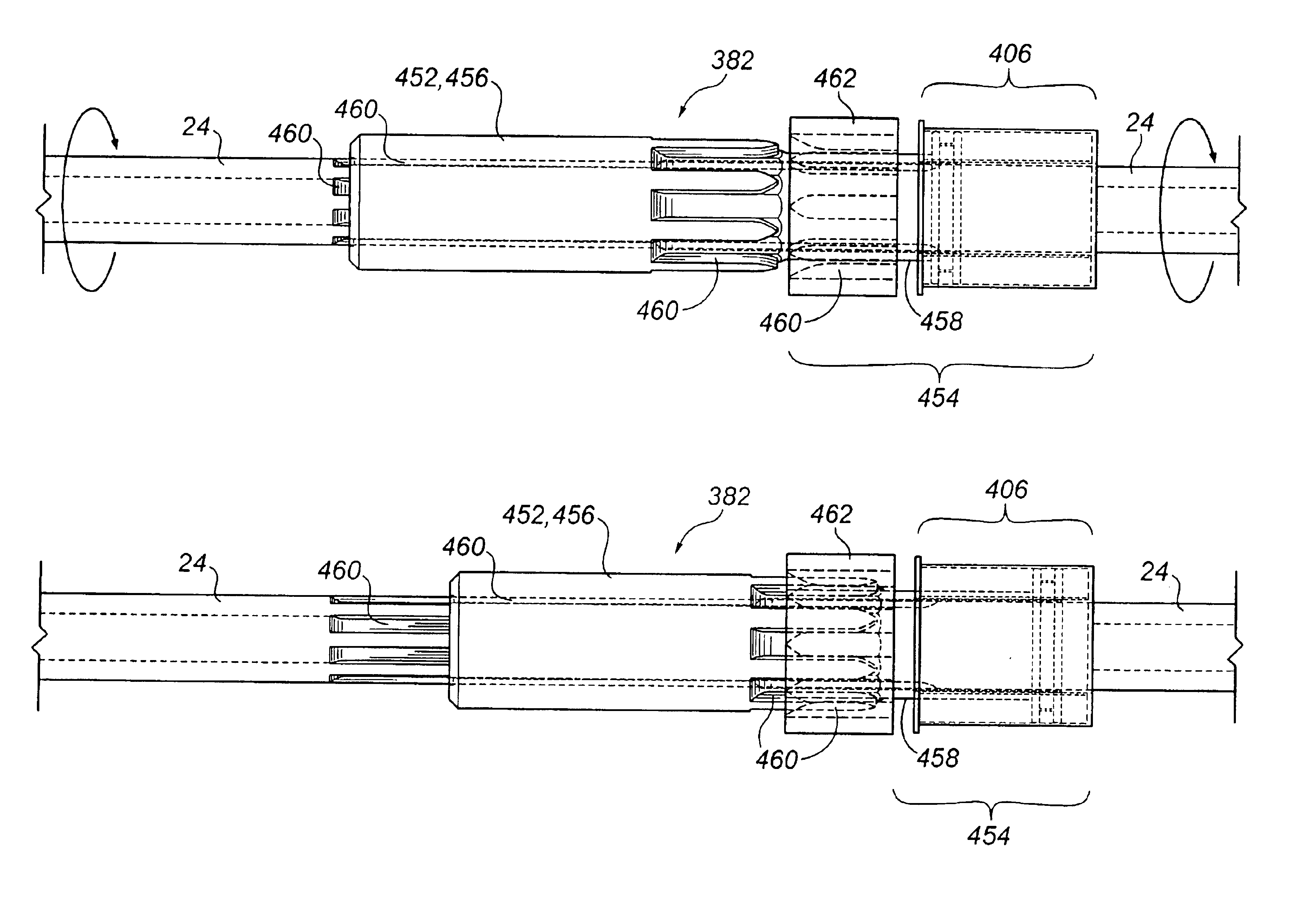
[0231]The second preferred embodiment of deflection assembly (92) is essentially a variation of deflection assembly (92). The difference between the two embodiments relates primarily to the design of the deflection mechanism (384).

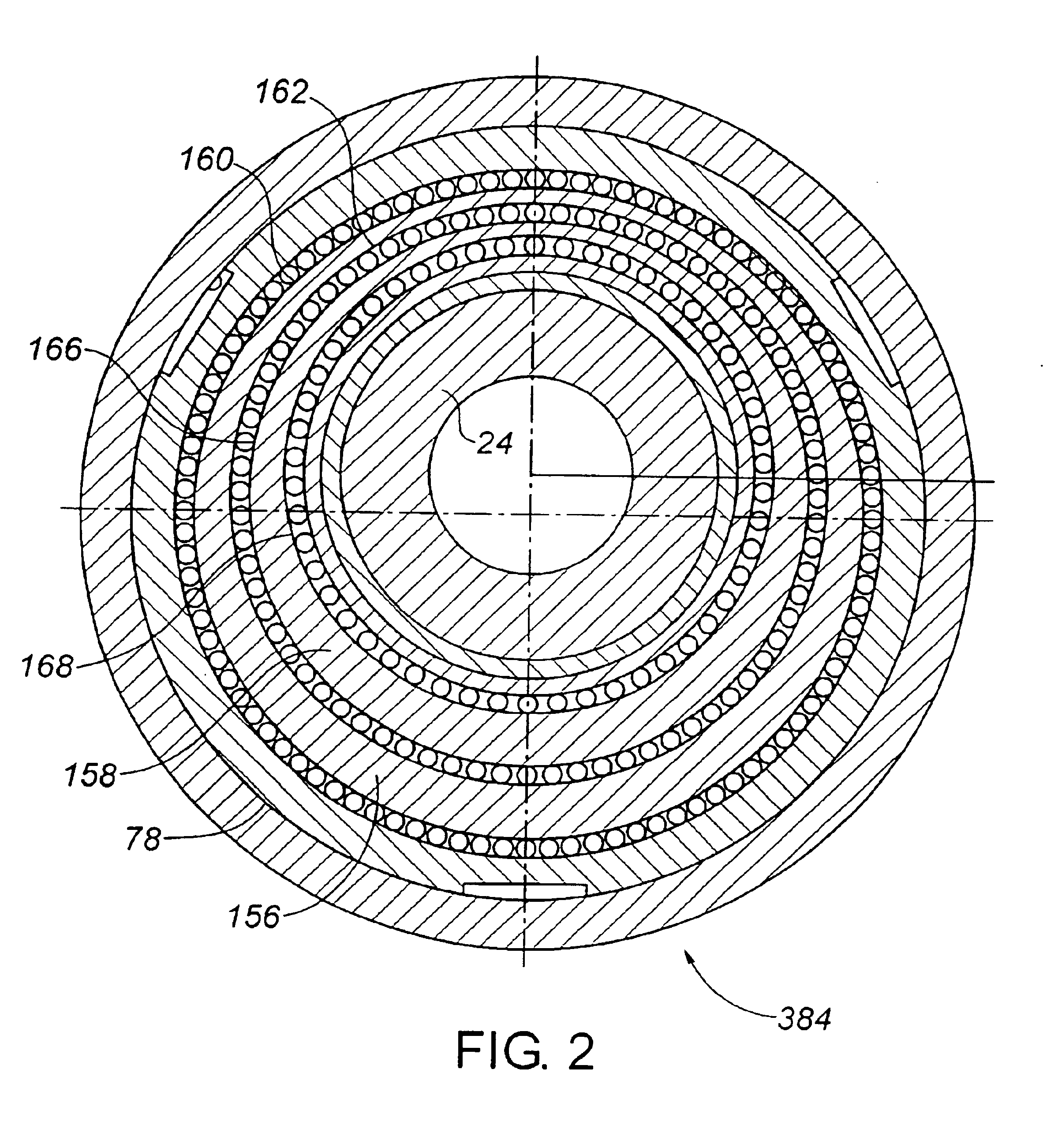
[0232]Specifically, the outer ring (156) of the first preferred embodiment is replaced with a rotary camming surface (408) and the inner ring (158) is replaced with a follower member (410). Rotation of the camming surface (408) relative to the follower member (410) will serve to deflect the drilling shaft (24). Coordinated rotation of both the camming surface (408) and the follower member (410) may serve to index the deflection mechanism (384) to provide a desired orientation for the bend in the drilling shaft (24).

[0233]Longitudinal movement of the deflection actuator (386) is therefore converted by the deflection linkage mechanism (388) and the deflection mechanism (384) into deflection of the drilling shaft (24). Similarly, longitudinal movement of the ...

third embodiment

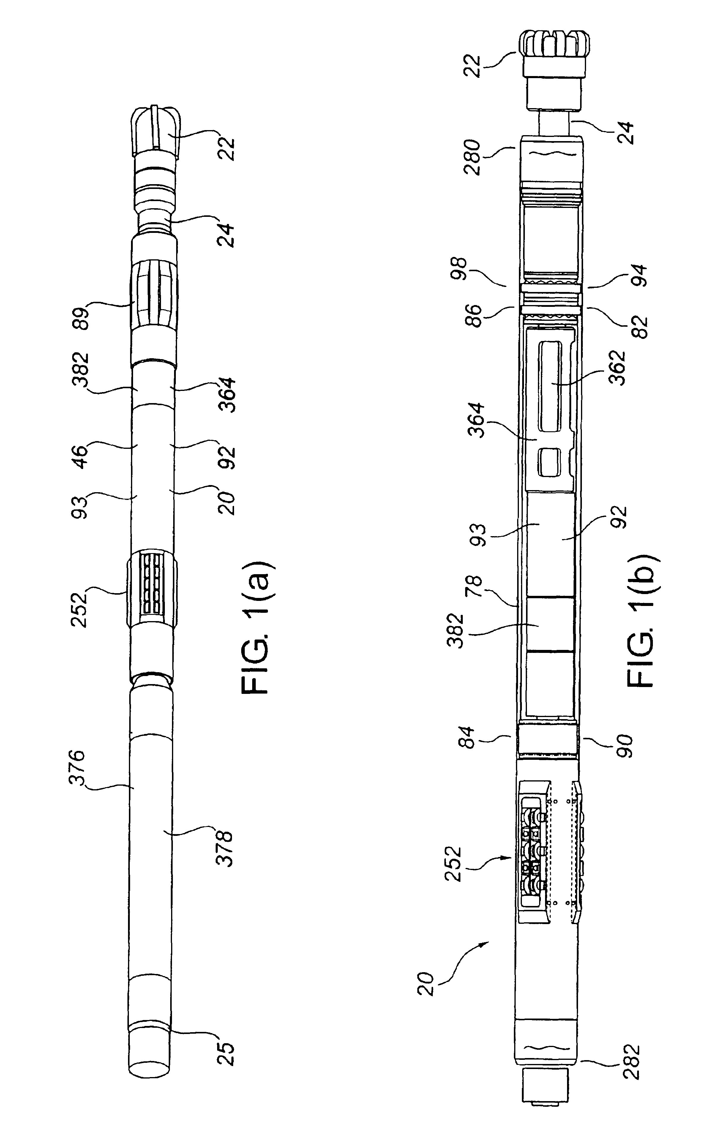
[0235]deflection assembly (92) may be implemented in many designs which fall within the scope of the invention. Two such designs are depicted in FIGS. 7-13.

[0236]In the third embodiment, the deflection mechanism (384) is comprised of at least one follower member (410), and the deflection linkage mechanism (388) is comprised of at least one longitudinally movable camming surface (412). The deflection actuator (386) is comprised of a longitudinally movable deflection actuator member (414).

[0237]The follower member (410) is capable of lateral movement between the housing (46) and the drilling shaft (24) but is not capable of longitudinal movement. The follower member (410) directly or indirectly engages the drilling shaft (24) so that lateral movement of the follower member (410) results in lateral movement of the drilling shaft (24).

[0238]The actuation of the deflection assembly (92) is powered by the power source (406). An exemplary power source is depicted in FIG. 7(c) and schematic...


PUM


Abstract

In a tool having an inner member supported within an outer member, wherein the tool defines a longitudinal axis, a device is provided for preventing relative rotation of the inner member and the outer member. The device is comprised of a locking mechanism and a locking actuator. The locking mechanism is positioned between the inner member and the outer member, wherein the locking mechanism is movable longitudinally between a first locking mechanism position in which the inner member and the outer member are disengaged and capable of relative rotation and a second locking mechanism position in which the inner member and the outer member are engaged and not capable of relative rotation. The locking actuator causes the locking mechanism to move longitudinally.

Description

FIELD OF INVENTION[0001]The present invention relates to improvements in a drilling direction control device, and in particular, to a shaft-to-housing locking device therefor.BACKGROUND OF INVENTION[0002]Directional drilling involves varying or controlling the direction of a wellbore as it is being drilled. Usually the goal of directional drilling is to reach or maintain a position within a target subterranean destination or formation with the drilling string. For instance, the drilling direction may be controlled to direct the wellbore towards a desired target destination, to control the wellbore horizontally to maintain it within a desired payzone or to correct for unwanted or undesired deviations from a desired or predetermined path.[0003]Thus, directional drilling may be defined as deflection of a wellbore along a predetermined or desired path in order to reach or intersect with, or to maintain a position within, a specific subterranean formation or target. The predetermined pat...

Claims


Application Information

Patent Timeline
IPC IPC(8): E21B23/02E21B7/06E21B7/08
CPCE21B7/062E21B7/067
Inventor KENT, GERALD EDWARD
Owner HALLIBURTON ENERGY SERVICES INC
Why Eureka
Try Eureka