Electric power steering assembly

a technology of electric power steering and assembly work, which is applied in the direction of stator/rotor body manufacturing, magnetic circuit shape/form/construction, transportation and packaging, etc., can solve the problems of rotor not being smoothly inserted in the inside circumference, assembly work cumbersome, and potential fear of rotor being brought into violent contact with magnets, so as to reduce the amount of assembly work.

Active Publication Date: 2007-06-26
JTEKT CORP
View PDF9 Cites 8 Cited by
  • Summary
  • Abstract
  • Description
  • Claims
  • Application Information

AI Technical Summary

Benefits of technology

[0010]According to the embodiment, the motor housing may be used as a guide jig during the assembly of the stator assembly. Specifically, when the stator assembly is inserted in the annular space between the motor housing and the rotor, the inside circumference of the motor housing can retain the stator assembly so as to restrict the stator assembly from radial movement despite magnetic attraction by magnets of the rotor.
[0011]Accordingly, the stator assembly may be mounted in the annular space quite easily. In addition, it is ensured that both the stator assembly and the rotor are positively prevented from contacting each other and causing damage on each other. Since the motor housing per se is used as the guide jig for the stator assembly, the removal of the jig following the assembly of the stator assembly is omitted, although the conventional art requires the removal of the jig. Thus, the labor involved in the assembly work may be reduced even further.

Problems solved by technology

According to the above publication, however, the following problems are encountered when the rotor is assembled in the stator.
Due to the magnetic force of magnets of the rotor, the rotor is attracted toward the stator so that the rotor is not smoothly inserted in the inside circumference of the stator.
This makes the assembly work cumbersome.
Furthermore, there is a potential fear of the rotor brought into violent contact with the magnets as attracted by the stator.
As a result, the rotor may be damaged.
However, this approach requires additional labor for removing the mounted jigs.

Method used


Image

  • Electric power steering assembly
  • Electric power steering assembly
  • Electric power steering assembly

Examples


Embodiment Construction

[0016]A preferred embodiment of the invention is described with reference to the accompanying drawings.

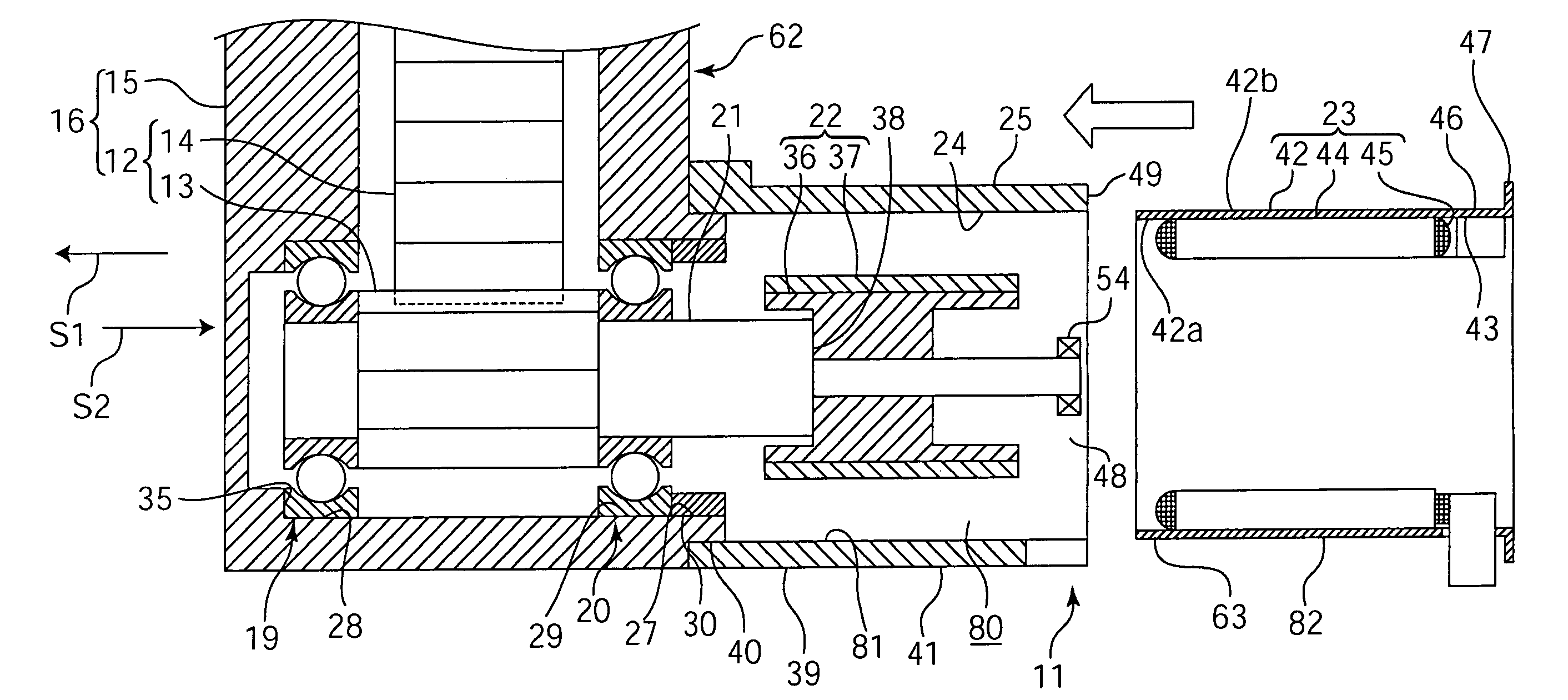
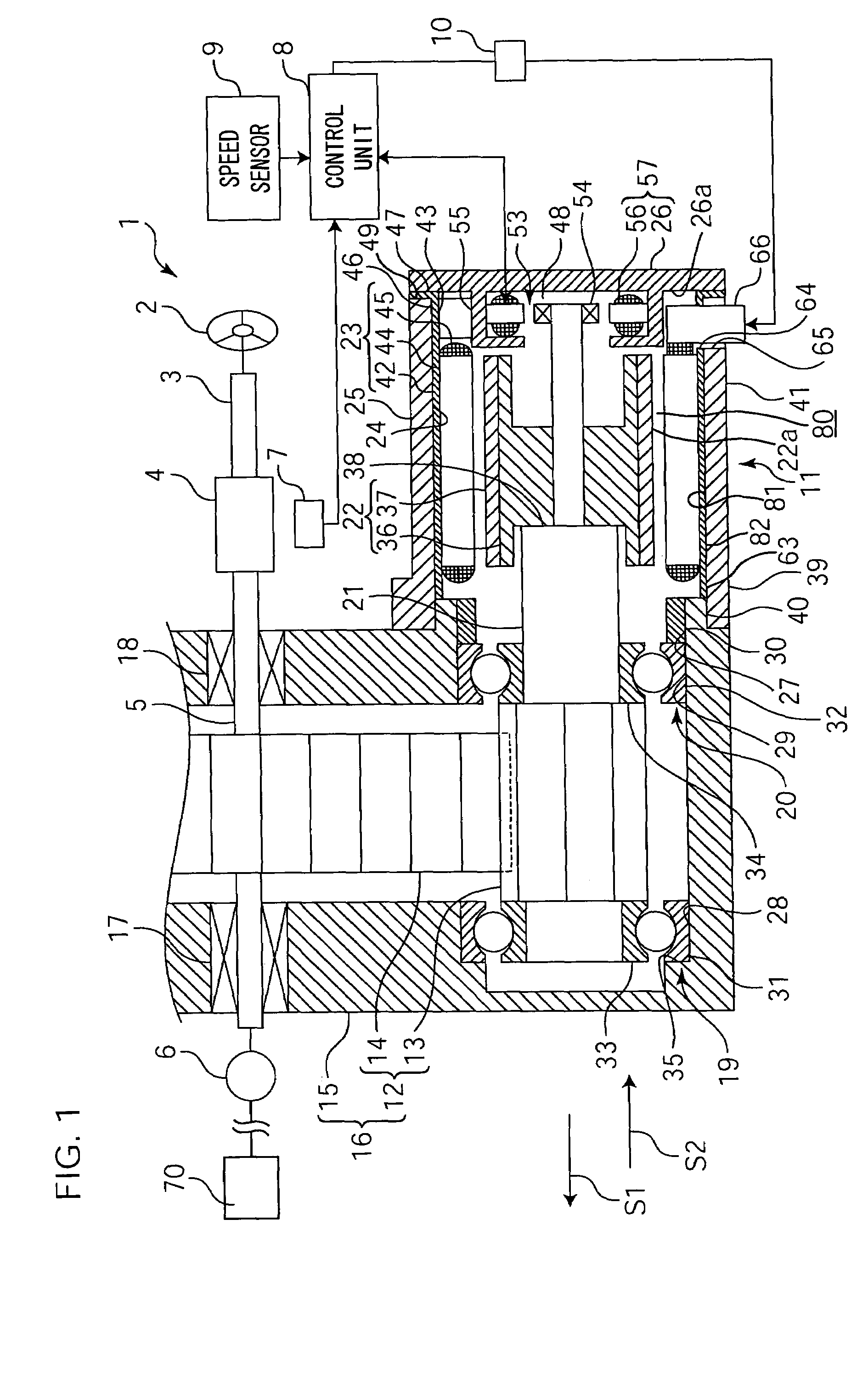
[0017]FIG. 1 is a schematic sectional view showing a general construction of an electric power steering assembly according to one embodiment of the invention. Referring to FIG. 1, an electric power steering assembly 1 includes a first steering shaft 3 integrally rotatably coupled to a steering member 2 such as a steering wheel, and a second steering shaft 5 coaxially coupled to the first steering shaft 3 via a torsion bar 4 as allowed to rotate relative to the first steering shaft.

[0018]The second steering shaft 5 is coupled with a steering mechanism (not shown) including a pinion, a rack shaft and the like via a universal joint 6, an intermediate shaft (not shown) and the like.

[0019]Thus, a torque produced by manipulating the steering member 2 is transmitted to a steering mechanism 70 such as a rack and pinion type steering mechanism via the first steering shaft 3, the torsion bar...


PUM

PropertyMeasurementUnit
speedaaaaaaaaaa
circumferenceaaaaaaaaaa
sizeaaaaaaaaaa

Abstract

An electric power steering assembly includes an electric motor, a reduction mechanism for reducing the speed of an output rotation of the electric motor, and a reduction-mechanism housing accommodating therein the reduction mechanism. The electric motor includes: an output shaft rotatably supported by the reduction-mechanism housing, a motor housing formed integrally with the reduction-mechanism housing, a rotor, and a stator assembly accommodated in an annular space defined between the rotor and the motor housing. When the stator assembly is assembled in the annular space via an opening at an end portion of the motor housing, a guided portion on an outside circumference of a stator yoke is guided by a guide portion on an inside circumference of the motor housing.

Description

BACKGROUND OF THE INVENTION[0001]1. Field of the Invention[0002]The present invention relates to an electric power steering assembly and a fabrication method thereof.[0003]2. Description of Related Art[0004]An electric power steering assembly is generally designed to transmit an output rotation of an electric motor to a steering mechanism via a reduction mechanism including a driving gear and a driven gear accommodated in a gear housing. The electric motor is normally constructed independently from the reduction mechanism. Hence, an output shaft is previously assembled to the electric motor (motor assembly) and then, the output shaft thus assembled is coupled with the driving gear of the reduction mechanism via a joint. More recently, however, a new design directed to the size reduction of the assembly has been proposed, wherein the joint is eliminated while the output shaft of the electric motor is integrally formed with the above driving gear (see, for example, Japanese Unexamined...

Claims


Application Information

Patent Timeline
Patent Type & Authority Patents(United States)
IPC IPC(8): H02K5/15B62D5/04H02K1/18H02K7/116H02K11/00H02K15/02H02K29/06
CPCB62D5/0403B62D5/0412Y10T29/49009B62D5/04
Inventor MATSUBARA, KENKUROUMARU, YOSHIKAZUNISHIZAKI, KATSUTOSHI
Owner JTEKT CORP
Why Eureka
Try Eureka