Pulse translation method from low to high voltage level in half and full bridge application

a technology of half bridge and high voltage, applied in pulse technique, power consumption reduction, oscillator generator, etc., can solve the problems of power dissipation, space occupation, cost increase, etc., and achieve the effect of reducing power dissipation

Inactive Publication Date: 2007-06-26
O2 MICRO INT LTD
View PDF5 Cites 43 Cited by
  • Summary
  • Abstract
  • Description
  • Claims
  • Application Information

AI Technical Summary

Benefits of technology

[0007]It is an object of the present invention to provide a

Problems solved by technology

The most important feature in the translation function when driving pulses from low voltage side to high voltage side is that using high v

Method used


Image

  • Pulse translation method from low to high voltage level in half and full bridge application
  • Pulse translation method from low to high voltage level in half and full bridge application
  • Pulse translation method from low to high voltage level in half and full bridge application

Examples


Embodiment Construction

[0023]While not wishing to be bound by example, the following Detailed Description will proceed with reference to a CCFL (Cold Cathode Fluorescent Lamp) as the load for the circuit of the present invention. The CCFL may serve as a backlight of a an LCD (liquid crystal display) panel, to illuminate the LCD panel. However, it will be apparent that the present invention is not limited only to driving one or more CCFLs, rather, the present invention should be broadly construed as a power converter circuit and methodology independent of the particular load for a particular application.

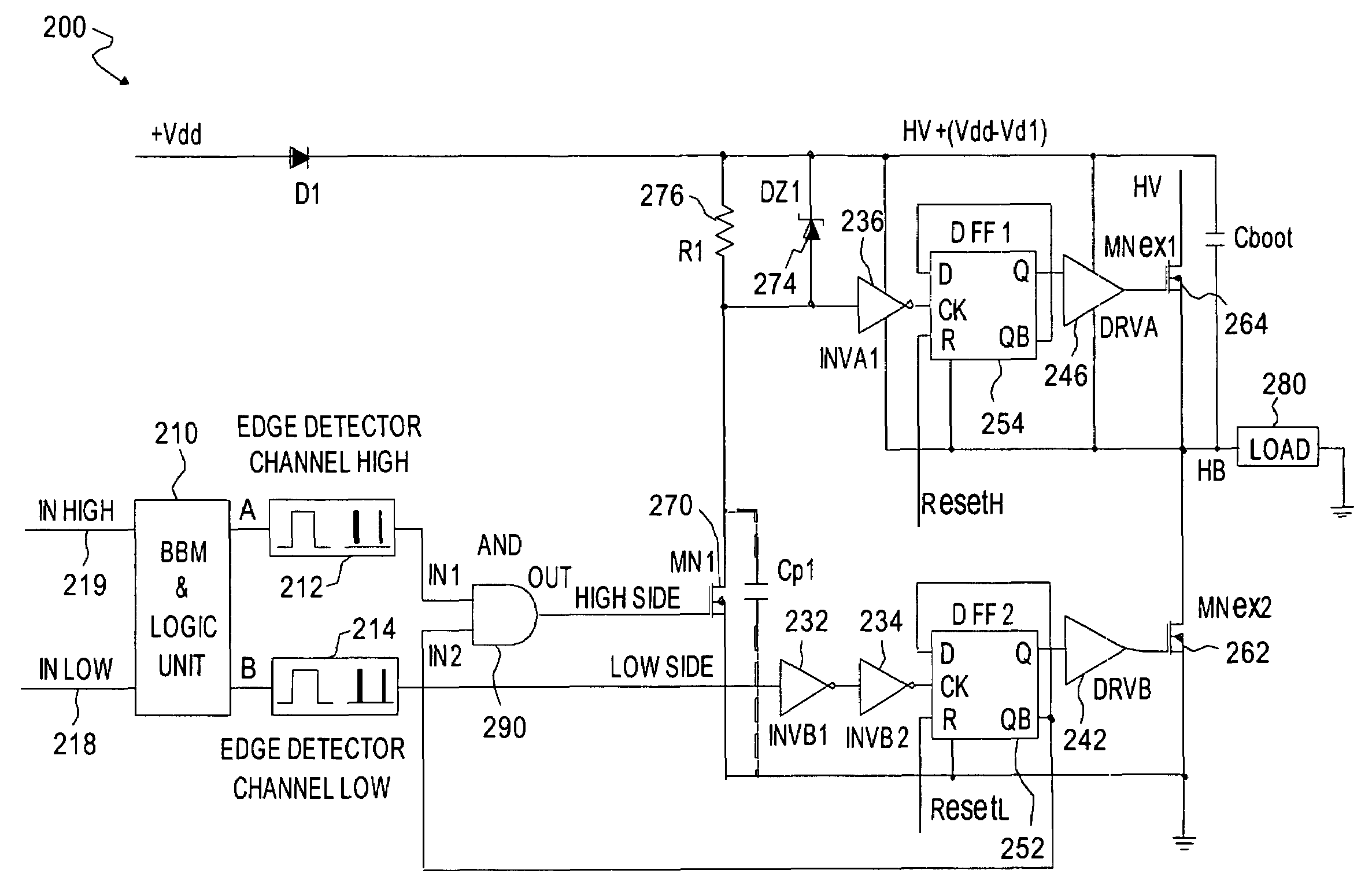
[0024]Referring to FIG. 2, a half bridge switching control circuit 200 is illustrated according to an embodiment of the present invention. The circuit 200 is connected to a load 280. For example, the load 280 may be a transformer which has a primary wiring and a second wiring. The primary wiring of the transformer is connected to the circuit 200 and the secondary wiring is connected to one or more CCFLs so ...


PUM


Abstract

A switched bridge circuit comprises a first switch, a second switch, and a non-overlapping pulse generator. The first switch is coupled to a load. The second switch is coupled to said load. The non-overlapping pulse generator is coupled to the first switch and the second switch and coupled to receive an input signal. The non-overlapping pulse generator in response to the input signal generates a first control signal and a second control signal that respectively control the first and second switches. The pulses in the first and second control signals are not overlapped so that the first and second switches are not simultaneously enabled.

Description

BACKGROUND OF THE INVENTION[0001]1. Field of the Invention[0002]The present invention relates to driving techniques for supplying power to a load, and more particularly, to driving circuitry in full bridge or half bridge inverter applications having non-overlapping pulses for vertical branches of the bridge, i.e., low voltage channel and high voltage channel.[0003]2. Description of the Related Art[0004]FIG. 1a illustrates a typical structure of level shift stage circuit 10 in the prior art. The level shift stage circuit 10 is provided with two HV DMOS transistors 14 and 16 for providing SET and RESET pulses to a RS flip flop 12. The input pulses applied to the Driving logic block 18 are decomposed into SET and RESET short pulses synchronous to the rising edge and falling edge of input signal. The level shifter, i.e., the transistors 14 and 16 generates two pulses, SETBAR and RESETBAR. These pulses are inverted once and are then applied to the RS flip flop 12. The output Q of the RS ...

Claims


Application Information

Patent Timeline
IPC IPC(8): H03K5/12
CPCH03K5/1534H03K19/0013
Inventor VIRGIL, GHEORGHIU IOAN
Owner O2 MICRO INT LTD
Why Eureka
Try Eureka