Compact monolithic capacitive discharge unit

a capacitive discharge unit, monolithic technology, applied in the direction of instruments, geological measurements, lighting and heating apparatus, etc., can solve the problems of not being usable for certain applications, not very rugged or compact, and limiting the attainment of the fast current discharge pulse which is required for certain applications

Active Publication Date: 2007-06-26
NAT TECH & ENG SOLUTIONS OF SANDIA LLC
View PDF8 Cites 12 Cited by
  • Summary
  • Abstract
  • Description
  • Claims
  • Application Information

AI Technical Summary

Benefits of technology

[0007]The present invention relates to a capacitive discharge unit (CDU) which comprises a ceramic capacitor for storing electrical energy; a thyristor switch attached onto one side of the ceramic capacitor and electrically connected thereto to discharge the electrical energy stored within the ceramic capacitor in response to a trigger signal provided to a gate of the thyristor switch; and a flyback charging circuit comprising a transformer (e.g. a low-temperature co-fired ceramic transformer) and a diode and which are attached onto the side of the ceramic capacitor opposite the thyristor switch to provide the electrical energy to th

Problems solved by technology

Conventional CDUs are generally not very rugged or compact and thus are not usable for certain applications having size constraints or requiring shock resistance.
Additionally, the inductance in wiring between a

Method used


Image

  • Compact monolithic capacitive discharge unit
  • Compact monolithic capacitive discharge unit
  • Compact monolithic capacitive discharge unit

Examples


first embodiment

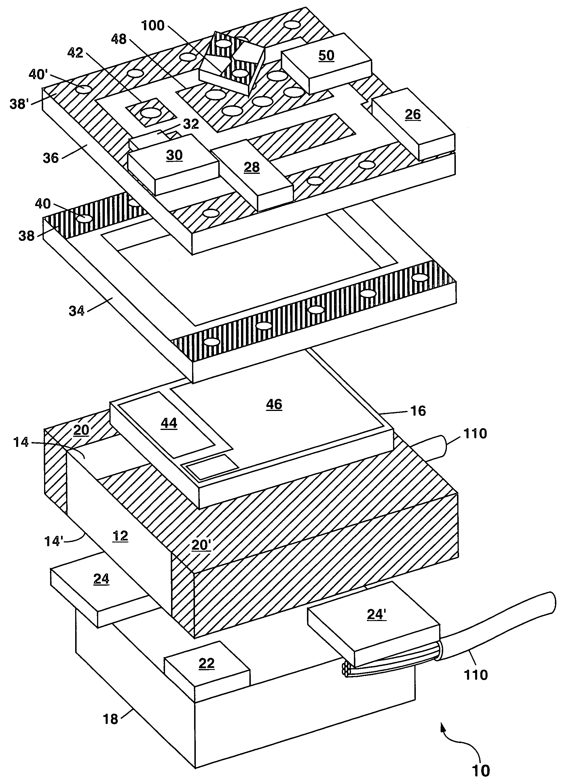
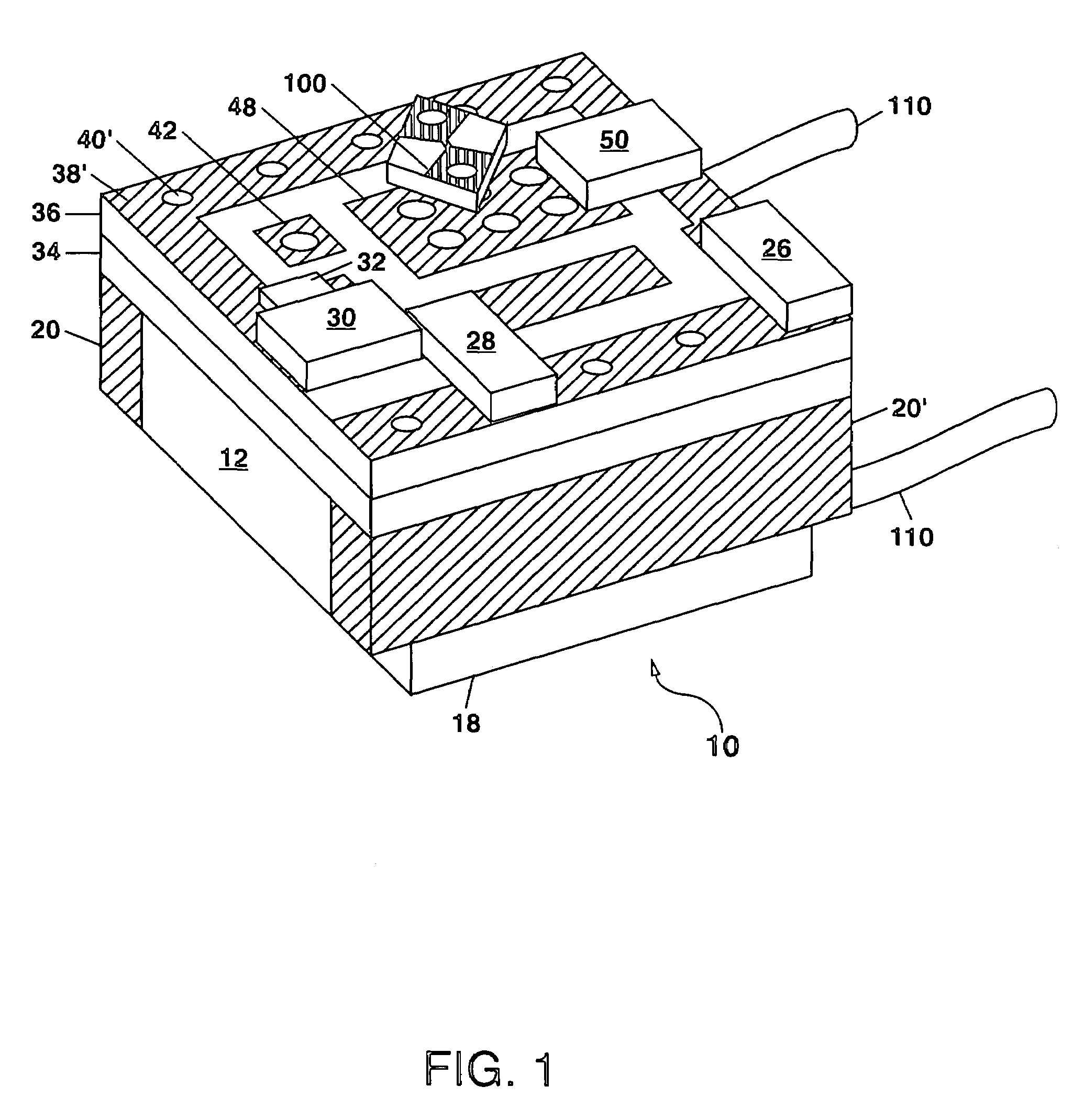
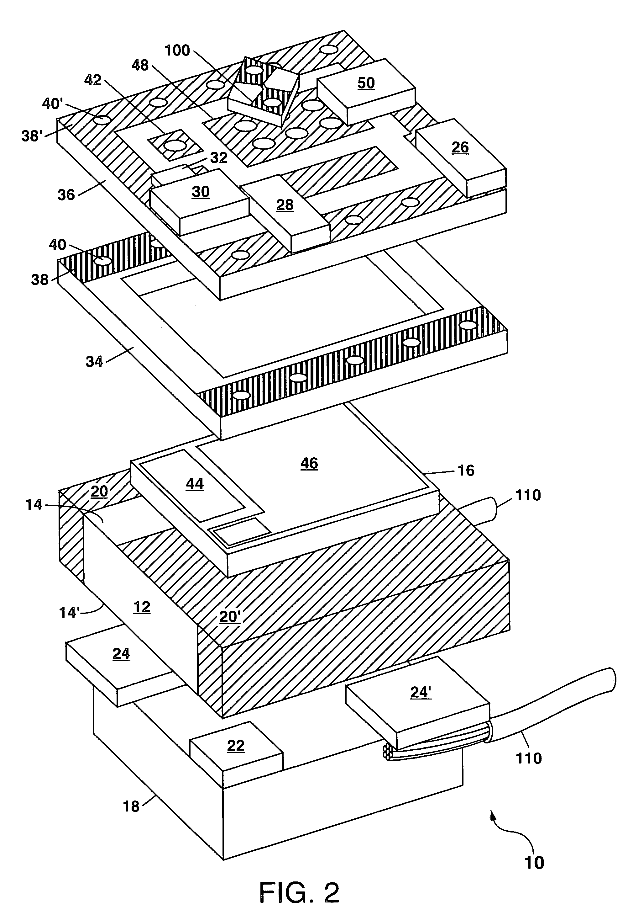
[0023]Referring to FIG. 1, there is shown a schematic perspective view of a monolithic capacitive discharge unit (CDU) 10 formed according to the present invention; and FIG. 2 shows an exploded view of the CDU 10 of FIG. 1. In FIGS. 1 and 2, the CDU 10 comprises a ceramic capacitor 12 for storing electrical energy, with the ceramic capacitor 12 having a pair of major surfaces 14 and 14′ whereon various elements of the CDU 10 can be attached to form a monolithic assembly which provides a low-inductance current path for discharge of the ceramic capacitor 12. A thyristor switch 16 is attached onto one major surface 14 of the ceramic capacitor 12, and a transformer 18 is attached onto the other major surface 14′.

[0024]In FIGS. 1 and 2, the ceramic capacitor 12 (indicated as C1 in FIG. 3) comprises a plurality of alternating metal plates which are stacked up and separated by an intervening dielectric material to form two sets of plates, with one set of plates being electrically connected...

second embodiment

[0039]In the CDU 10 of the present invention, the trigger input electrode 42 can extend outward from the ceramic lid 36 as shown in FIGS. 5 and 6 to facilitate soldering of an external wire thereto. In this case, a via 40′ can be provided through the ceramic lid 36 and metallized to allow the trigger input electrode 42 to be electrically connected to a patterned metallization on the lower surface of the lid 36 and therefrom to the gate 44 on the thyristor switch 16.

[0040]The various elements of the CDU 10 of FIGS. 5 and 6 can be stacked and bonded together (e.g. using a solder reflow process or an electrically-conductive epoxy) to form the completed CDU 10. The load 100 (e.g. a detonator) can be bonded together with the CDU 10, or can be added at a later time.

[0041]In other embodiments of the present invention, the various resistors 26, 28 and 30 and the smoothing capacitor 32 can be directly integrated into the LTCC transformer 18. This can be done, for example, as shown in FIG. 7 ...


PUM


Abstract

A compact monolithic capacitive discharge unit (CDU) is disclosed in which a thyristor switch and a flyback charging circuit are both sandwiched about a ceramic energy storage capacitor. The result is a compact rugged assembly which provides a low-inductance current discharge path. The flyback charging circuit preferably includes a low-temperature co-fired ceramic transformer. The CDU can further include one or more ceramic substrates for enclosing the thyristor switch and for holding various passive components used in the flyback charging circuit. A load such as a detonator can also be attached directly to the CDU.

Description

GOVERNMENT RIGHTS[0001]This invention was made with Government support under Contract No. DE-AC04-94AL85000 awarded by the U.S. Department of Energy. The Government has certain rights in the invention.FIELD OF THE INVENTION[0002]The present invention relates in general to capacitive discharge units (CDUs) for electrical energy storage and release, and in particular to a compact rugged CDU formed by monolithically integrating an energy storage capacitor together with a semiconductor thyristor switch and a flyback charging circuit.BACKGROUND OF THE INVENTION[0003]Capacitive discharge units (CDUs) find use in a variety of applications where a short burst of a large electrical current is required. This includes the initiation of detonators for commercial or military applications, the initiation of flashlamps, the initiation of plasma discharges, etc. Conventional CDUs are generally not very rugged or compact and thus are not usable for certain applications having size constraints or req...

Claims


Application Information

Patent Timeline
IPC IPC(8): F23Q3/00
CPCF42B3/121
Inventor ROESLER, ALEXANDER W.VERNON, GEORGE E.HOKE, DARREN A.DE MARQUIS, VIRGINIA K.HARRIS, STEVEN M.
Owner NAT TECH & ENG SOLUTIONS OF SANDIA LLC
Why Eureka
Try Eureka