Method for forming image and image forming apparatus

a technology of image forming apparatus and method, which is applied in the direction of electrographic process apparatus, instruments, developers, etc., can solve the problems of high electric field required for the transfer of toner, high risk of aerial discharge, and difficult to manufacture toner, etc., and achieves excellent transfer efficiency, high degree of automation, and high degree of automation.

Active Publication Date: 2007-06-26
KK TOSHIBA +1
View PDF5 Cites 6 Cited by
  • Summary
  • Abstract
  • Description
  • Claims
  • Application Information

AI Technical Summary

Benefits of technology

[0008]An object of the present invention is to provide an image forming apparatus which is excellent in transferring efficiency, is applicable even to a cleaner-less process, and is capable of forming a highly precise image which is substantially free from dusts.
[0009]Another object of the present invention is to provide a method of forming an image, which is excellent in transferring efficiency, is applicable even to a cleaner-less process, and makes it possible to form a highly precise image which is substantially free from dust.

Problems solved by technology

However, since this distribution of toner adhesive force is confined to an extremely narrow range, e.g. the a standard deviation σ is required to be not more than 0.3×10⁻⁸ as the average adhesive force is 6×10⁻⁸ N, the manufacture of toner becomes very difficult.
Further, although it may be possible to enlarge the distribution of toner adhesive force to a certain extent by increasing the average adhesive force, if the toner adhesive force is increased too high, the transferring electric field required for the transfer of toner would become very high, thereby giving rise to risk of aerial discharge.
According to this measuring method however, it is impossible to grasp the behavior of the toner which is weak in adhesive force, i.e., the toner which can be separated from an image carrier as the toner is subjected to weak transferring electric field immediately before the toner is introduced into the transferring nip.
Because of these reasons, even with the employment of this technique, there are problems with regard to the transferring efficiency and quality of image.
Therefore, if the quantity of residual toner after the transferring step is large, it may become causes for generating a defective image due to the incidents that the light source for forming a latent image may be obstructed, the recovery of toner by the developing device may become insufficient, and the generation of undesirable retransferring.
Once this reversely transferred toner is recovered by the developing device in the cleaner-less process, the toner having the color of the developing station of the preceding stage is permitted to enter into the developing device of the succeeding stage, thereby making it impossible to perform the management of color if the toner entering the developing device of the succeeding stage is increased.

Method used


Image

  • Method for forming image and image forming apparatus
  • Method for forming image and image forming apparatus
  • Method for forming image and image forming apparatus

Examples


experimental examples

[0116]Four kinds of toners and two kinds of carriers were prepared as follows.

[0117]Preparation of Toner A:

[0118]28 parts by weight of polyester resin, 7 parts by weight of Carmine 6B, 5 parts by weight of rice wax and one part by weight of carnauba wax were mixed and kneaded by making use of Kneadex (YPK Co., Ltd.) to prepare a master batch. After being subjected to coarse crushing, the master batch is further mixed with 58 parts by weight of polyester resin and one part by weight of CCA. The resultant mixture was then kneaded, coarsely pulverized and finely pulverized to obtain particles. Then, by means of elbow jet classification, parts of the particles having a particle diameter of 8 μm or more and having a particle diameter of 3 μm or less were removed to obtain toner particle having a volume average particle diameter of 5.3 μm.

[0119]To 100 parts by weight of the toner particle thus obtained, 3.5 parts by weight of silica having a primary particle diameter of 20 nm was added as...

experiment 1

[0130](1) A Combination of Toner A and Carrier α:

[0131]9 parts by weight of Toner A was mixed with 91 parts by weight of Carrier α to obtain a developing agent.

[0132]The developing agent thus obtained was applied to an image forming apparatus having the same structure as shown in FIG. 5 except that a film having the same photosensitive layer as the photoreceptor was wound around the surface of photoreceptor, thereby performing electrification, exposure and development of toner.

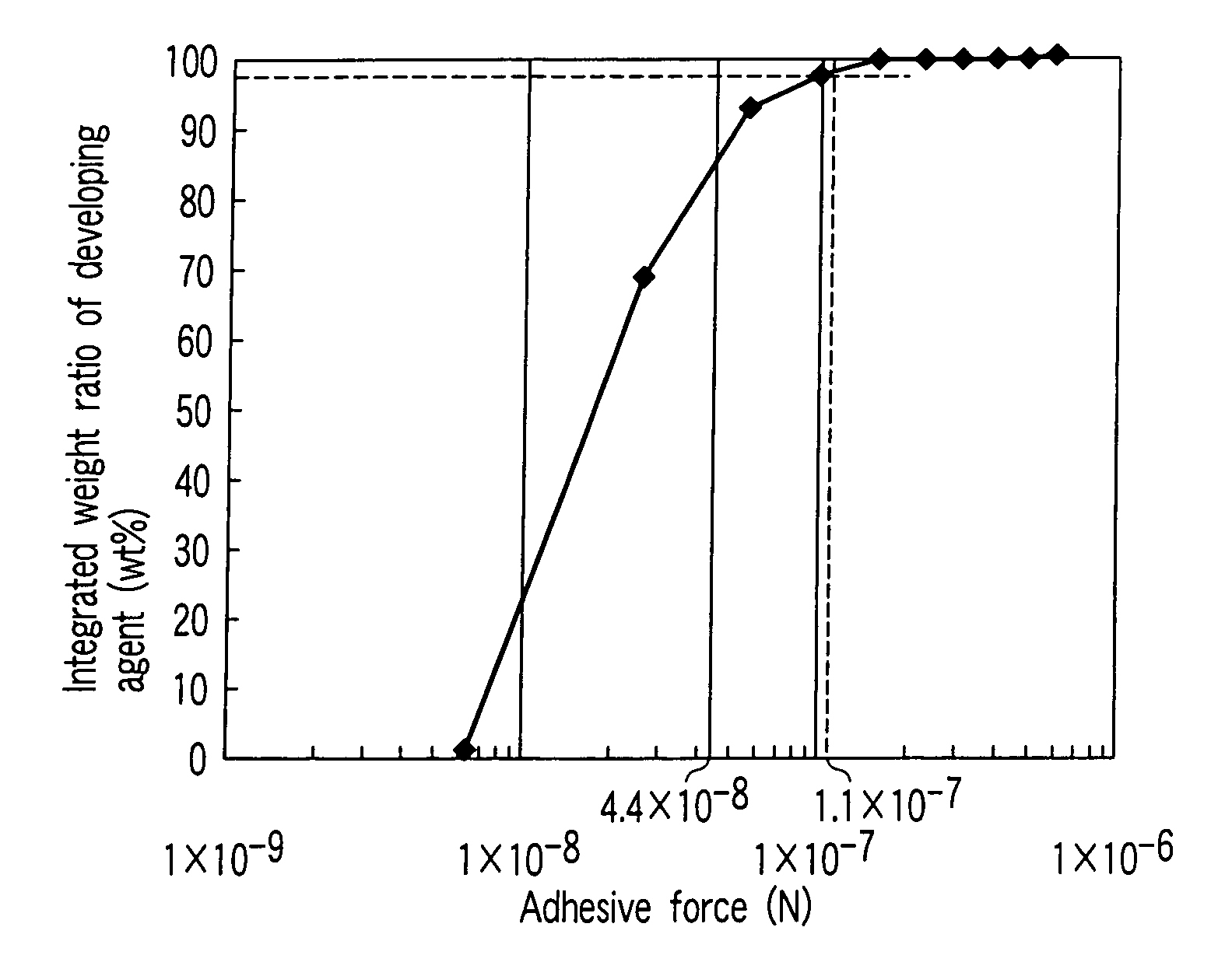
[0133]The film where the toner was developed was taken out as it is and the distribution of adhesive force of toner was measured. The results are shown in FIG. 9.

[0134]FIG. 9 shows a graph illustrating one example of a first distribution of adhesive force to be employed in the present invention. This graph illustrates the relationship between the adhesive force of the developing agent and the added weight ratio of the developing agent having the aforementioned adhesive force.

[0135]As shown in FIG. 9, an averag...

experiment 2

[0148](1) A Combination of Toner C and Carrier β:

[0149]11 parts by weight of Toner C was mixed with 89 parts by weight of Carrier β to obtain a developing agent.

[0150]The developing agent thus obtained was applied to an image forming apparatus having the same structure as shown in FIG. 6 except that a film having the same photosensitive layer as the photoreceptor was wound around the surface of photoreceptor, thereby measuring the distribution of adhesive force, the quantity of residual toner, and performing the life test in the same manner as in Experiment 1.

[0151]As a result, an average value of the adhesive force was 1.04×10⁻⁷ (N). Further, the adhesive force which was 2.5 times as high as this average value was 2.6×10⁻⁷ (N). The ratio of the developing agent having an adhesive force of not less than 2.6×10⁻⁷ (N) was 1.5% by weight. The quantity of the residual toner was 1.4% by weight.

[0152]Further, when the formation of image was performed by making use of this developing agent...


PUM


Abstract

The developing agent is selected to have a distribution of adhesive force to the surface of an image carrier, which is configured such that the ratio of the developing agent having an adhesive force which is not less than 2.5 times as high as an average value of a distribution of adhesive force is 3% by weight or less based on an entire weight of the developing agent.

Description

BACKGROUND OF THE INVENTION[0001]This invention relates to an image forming apparatus for developing an electrostatic image or a magnetic latent image in an electrophotographic method, an electrostatic printing method, or a magnetic recording method, and also to a method for forming an image where the image forming apparatus is employed.[0002]When an image is to be formed by means of an electrophotographic system and if a two-component dry developing method is to be employed, a particulate toner is delivered from a developing apparatus and transferred via a carrier, an image carrier and, optionally, a transfer medium such as in intermediate transferring member, etc., to a recording material. Then, the toner on the recording material is subjected to heat and pressure so as to be fixed on the recording material. The toner in this case is enabled to adhere to each transferring medium through electrostatic force derived from the quantity of electric charge each toner particle has, van d...

Claims


Application Information

Patent Timeline
Patent Type & Authority Patents(United States)
IPC IPC(8): G03G15/06
CPCG03G9/0821G03G9/0823G03G15/06G03G2221/0005
Inventor SHIMMURA, SHOKO
Owner KK TOSHIBA
Why Eureka
Try Eureka