Method for compensating and out-of-balance condition of a rotating body

a technology of rotating bodies and out-of-balance conditions, which is applied in the field of compensation of out-of-balance conditions of rotating bodies, can solve the problems of time-consuming and expensive procedures, and the known methods are not suited to the balancing of the measurement device of tomography apparatuses, and achieves the effect of small expenditur

Active Publication Date: 2007-06-26
SIEMENS HEALTHCARE GMBH
View PDF24 Cites 9 Cited by
  • Summary
  • Abstract
  • Description
  • Claims
  • Application Information

AI Technical Summary

Benefits of technology

[0018]As used herein, the “axis” of the data acquisition device means its geometrical axis or rotational axis. The rotational axis can in practice deviate from a center-of-gravity axis proceeding through the center of gravity of the measurement device. As a consequence of such a deviation, the measurement device exhibits an out-of-balance condition give rotation around the rotation axis. By an adjustment of the rotational axis of the data acquisition device with regard to the invariable axis of the bearing accommodating the data acquisition device, it can be achieved that tho center-of-gravity axis is brought into agreement with the axis of the bearing, and thus the out-of-balance condition of the data acquisition device is compensated.
[0020]Because the adjustment elements are disposed in two parallel planes axially separated from one another, it is possible to compensate radial out-of-balance vectors.
[0022]According to a further embodiment, a further sensor is provided to determine the rotation angle of the data acquisition device with regard to the stationary unit. This enables a continuous determination of the rotation angle, and thus a simplified determination of the position of the out-of-balance condition of the data acquisition device. It is thus particularly simple to calculate the vectors opposite to the out-of-balance vectors.

Problems solved by technology

This procedure thus is time-consuming and expensive.
Independent of this, some of the known methods are not suited for balancing of a measurement device of tomography apparatuses.

Method used


Image

  • Method for compensating and out-of-balance condition of a rotating body
  • Method for compensating and out-of-balance condition of a rotating body
  • Method for compensating and out-of-balance condition of a rotating body

Examples


Embodiment Construction

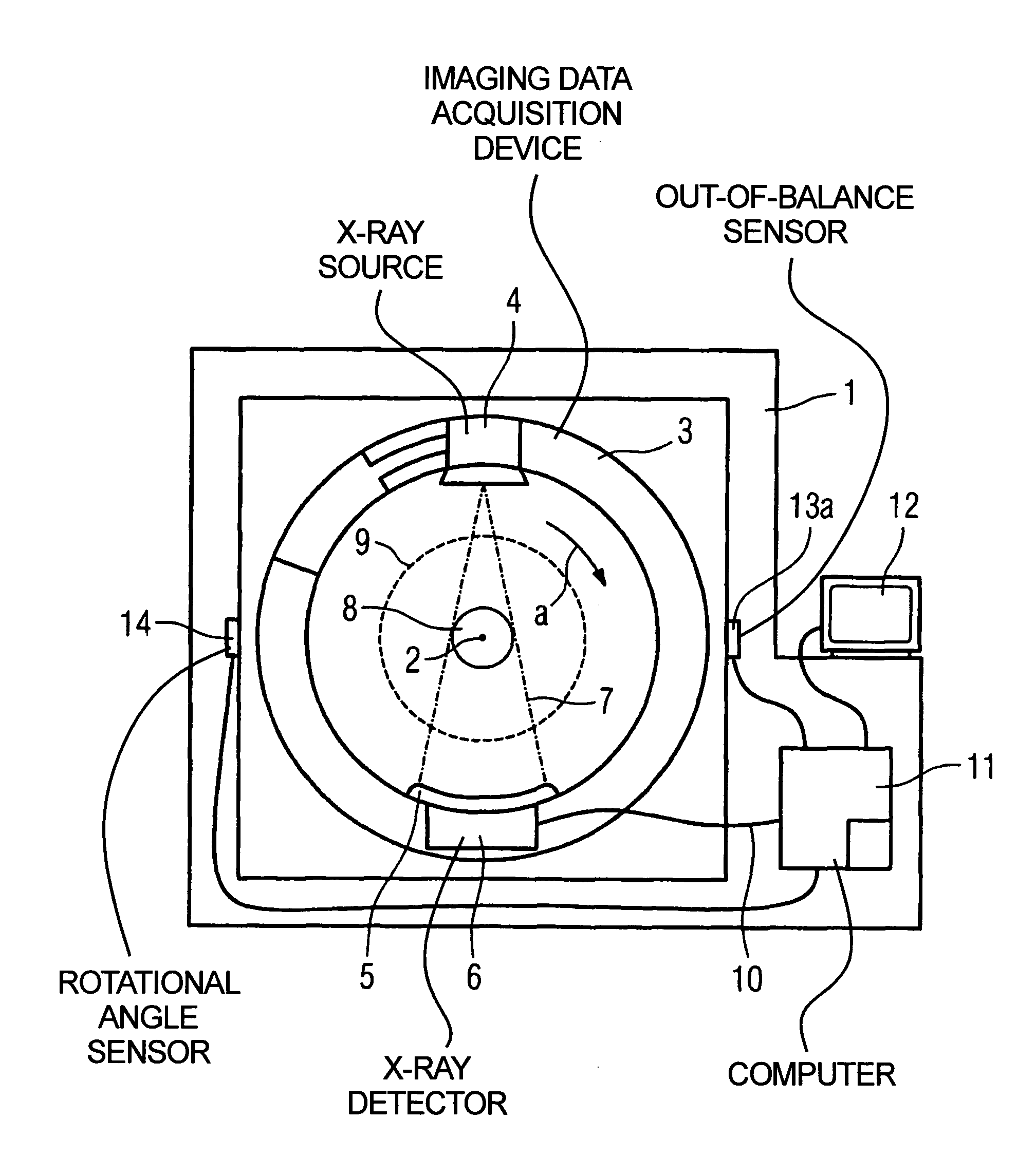
[0027]FIG. 1 schematically shows a side view of an x-ray tomography apparatus with a stationary unit 1. An annular imaging data acquisition device 3 (gantry) is accommodated on the stationary unit 1 such that it can rotate around a rotation axis 2 disposed at a right angle to the plane of the drawing. A rotational direction of the data acquisition device 3 is designated with the arrow a. An x-ray source 4 and an x-ray detector 5 with downstream evaluation electronic 6 are mounted on the data acquisition device 3 opposite to each other. A beam fan 7 radiated by the x-ray source 4 defines a circular measurement field 8 given a rotation of the data acquisition device 3. The measurement field 8 is located within a patient opening 9 indicated with the dashed line. In particular the evaluation electronics 6 are connected with a computer 11 via a slip ring contact 10 (indicated schematically), which computer 11 has a monitor 12 for display of data. First sensors for measurement of vibratio...


PUM


Abstract

In a method for compensation of an out-of-balance condition of an imaging data acquisition device, rotatable around a patient opening of a stationary unit of a tomography apparatus, such as an x-ray computed tomography apparatus or an ultrasound tomography apparatus, the data acquisition device being rotatably mounted such that it can rotate around an axis in a bearing of the stationary unit, vibrations transferred to the stationary unit by the out-of-balance condition of the data acquisition device, at least one of the out-of-balance vectors causing the out-of-balance condition is determined from the vibration measurement, and the axis of the data acquisition device is adjusted with regard to an axis of the bearing to compensate the out-of-balance condition.

Description

BACKGROUND OF THE INVENTION[0001]1. Field of the Invention[0002]The invention concerns a method for compensation of the out-of-balance condition of a rotating body, such as a data acquisition device of a tomography apparatus.[0003]2. Description of the Prior Art[0004]An x-ray computed tomography apparatus is known from German OS 101 08 065. A data acquisition device or gantry, mounted such that it can be rotated around a horizontal rotational axis, is accommodated in a stationary mount. A sensor to detect an out-of-balance (unbalanced) condition of the data acquisition device is provided on the stationary mount. The sensor is connected with a device to calculate the position or positions of the rotatable data acquisition device at which a compensation weight or weights should be applied to compensate the out-of-balance condition. The balancing can ensue without the use of a specific balancing device, but a trained person is required to implement the balancing procedure, in particula...

Claims


Application Information

Patent Timeline
Patent Type & Authority Patents(United States)
IPC IPC(8): G01M1/38A61B6/03G01M1/36
CPCA61B6/035A61B6/586G01M1/36
Inventor DANZ, GUNTERMULLER, HANS-JURGEN
Owner SIEMENS HEALTHCARE GMBH
Why Eureka
Try Eureka