PC card

a technology of printed circuit boards and pc cards, which is applied in the direction of electrical apparatus casings/cabinets/drawers, coupling device connections, instruments, etc., can solve the problems of increasing manufacturing costs, reducing the height of electric components to be mounted on the bottom face of the printed circuit board b>3/b>, and achieving high reliability

Active Publication Date: 2007-07-03
PANASONIC CORP
View PDF6 Cites 12 Cited by
  • Summary
  • Abstract
  • Description
  • Claims
  • Application Information

AI Technical Summary

Benefits of technology

[0010]With the foregoing in view, it is an object of the present invention to provide a highly reliable PC card where contact of the terminal sections of the SD memory card and the contacts of the connectors are more stable, with four SD memory cards being installed internally. It is another object of the present invention to provide a PC card of which the internally installed SD memory cards are hardly affected by static electricity from the outside.
[0012]According to the present invention, the connectors and the four SD memory cards can be secured compactly on the printed circuit board with maintaining positional accuracy by pressing and securing the SD memory cards on the printed circuit board by the pressing members, and a contact failure between the terminal sections and the contacts hardly occurs, therefore the four SD memory cards can be housed in the PC card with securing reliability. Also the SD memory cards can be secured after mounting the connectors on the printed circuit board, so assembly is easy, and also the SD memory cards can be removed if the pressing members are removed from the printed circuit board, so superb PC cards having easy maintenance can be provided.

Problems solved by technology

This processing increases the manufacturing cost.
As a result, the gap between the bottom face of the printed circuit board 3 and the bottom face of the PC card decreases, and the height of the electric components to be mounted on the bottom face of the printed circuit board 3 is limited for this amount, and the components to be mounted are restricted.
In this case however, the connectors 4 and the pressing member 6 must be secured to the printed circuit board 3 in a state where the SD memory cards 5 are inserted, so mounting of the connectors 4 is difficult, and an exchange of the SD memory cards 5 is difficult because the connectors 4 must be removed first.

Method used


Image

  • PC card
  • PC card
  • PC card

Examples


embodiment 1

(Background Description)

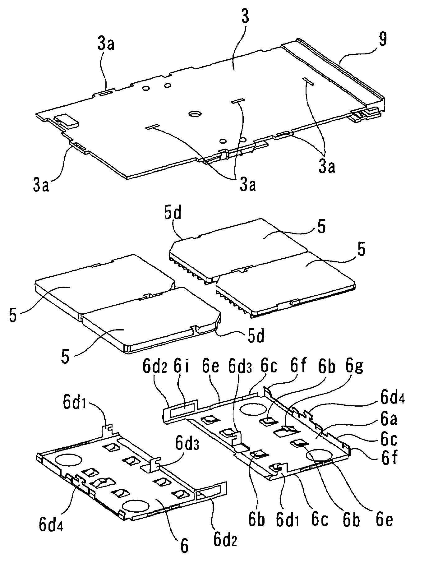
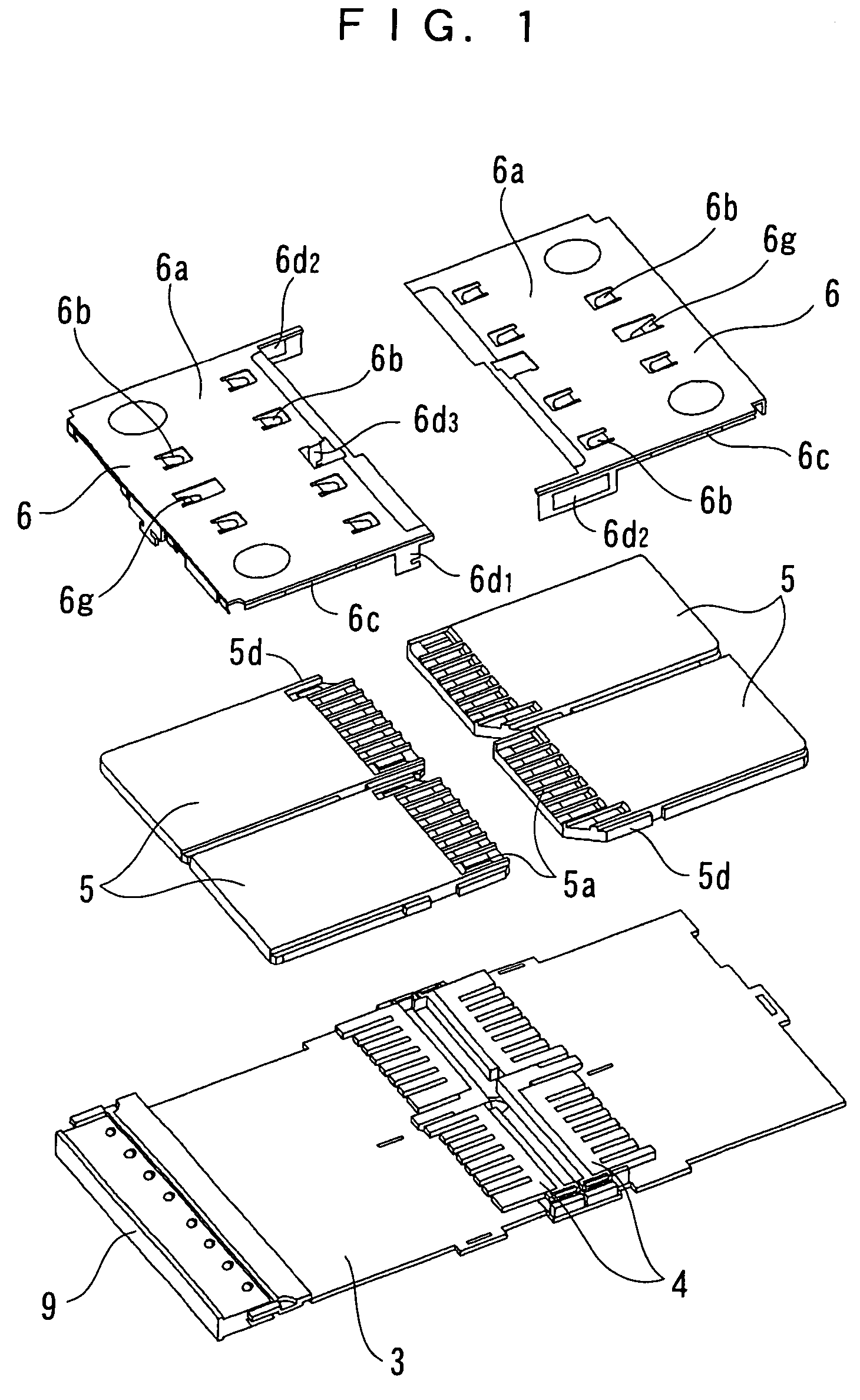
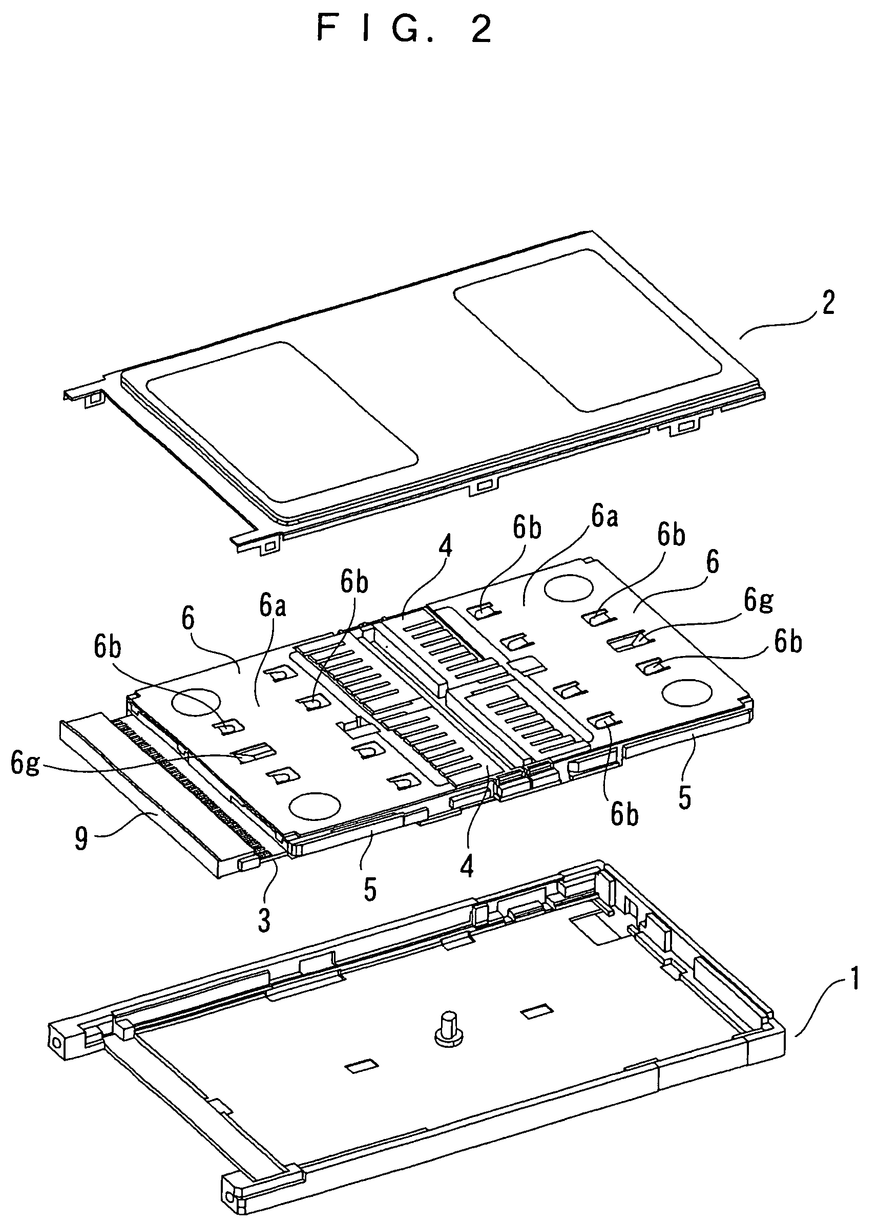
[0049]FIG. 1 is an exploded perspective view depicting the major areas of the constituent elements of the PC card according to the present invention, FIG. 2 is an exploded perspective view depicting the constituent elements of the PC card, and FIG. 3 is an exploded perspective view depicting the major areas of the PC card according to the present invention viewed from the rear side. The same constituent elements as those of the prior art are denoted with the same reference numerals, for which detailed description is omitted.

[0050]In FIG. 1-FIG. 3, the difference from the prior art is that the pressing members 6 are disposed. The pressing members 6 are made of a metal elastic body, and are disposed over the two SD memory cards 5 inserted into the connectors 4 respectively, so as to cover these two SD memory cards 5.

[0051]The present invention faced the problem where a simple configuration of covering the pressing members 6 on the SD memory cards 5 of the PC ca...

embodiment 2

[0093]FIG. 10 is an exploded perspective view using plate members according to the second embodiment. In FIG. 10, the difference from the first embodiment is that the plate members 12 are added.

[0094]The plate member is comprised of a square main body and string section. On the plate member 12, holes 12a are created substantially at the same positions as holes 3a on the printed circuit board 3, and the third and fourth engagement pieces 6d3 and 6d4 of the pressing member penetrate through the holes 3a of the printed circuit board 3 and the holes 12a of the plate member 12, then the engagement pieces are bent on a horizontal plane or in the direction of the plate member 12 at the notch sections, and are pressed and secured from the end face of the plate member 12.

[0095]In the present invention, the tips of the engagement pieces 6d3 and 6d4 of the pressing member 6 are bent and secured to the plate member 12, but it is also possible that long holes are created in the sliding direction...

embodiment 3

[0098]FIG. 11 is an exploded perspective view of another embodiment of a method of securing the pressing member to the printed circuit board. As mentioned above, the pressing member 6 holds the SD memory cards 5 and secures them to the printed circuit board 3. According to the present embodiment, the width of the hole 6i of the second engagement piece 6d2 is created so that the protrusion 5d of the SD memory card can engage to the hole with almost no gap, and the width of the protrusion 3e of the printed circuit board 3, on the other hand, is created to be narrower than the hole 6i. At the tips of the third engagement piece 6d3 and the fourth engagement piece 6d4, notch sections, having a groove width which is slightly larger than the thickness of the printed circuit board 3, are created. Long holes 3b that can engage to the third engagement piece 6d3 and the fourth engagement piece 6d4 are created on the printed circuit 3.

[0099]During assembly, the SD memory cards 5 are set in adva...


PUM


Abstract

An object of the present invention is to provide a PC card having four SD memory cards therein, which maintains the positional accuracy of the SD memory cards and connectors, and has high contact stability. The PC card includes in its case a printed circuit board (3), connectors (4) secured to the printed circuit board (3), and pressing members (6) secured to the printed circuit board (3). The pressing members (6) hold two SD memory cards respectively, while pressing them to the printed circuit board (3) and the connector (4).

Description

TECHNICAL FIELD[0001]The present invention relates to a PC card that is used for portable information processing equipment, for example, and more particularly to a configuration of a PC card that has a plurality of SD memory cards installed therein so as to be used as a large capacity memory card.BACKGROUND ART[0002]Recently PC card type adapters are used for installing memory cards, using such flash memories as SD memory cards, to a personal computer. In some cases a plurality of memory cards can be simultaneously installed in one adapter (e.g. see JP9-102019 A).[0003]On the other hand, the capacities of memory cards are increasing, and more equipment records / reproduces large volumes of data, such as images, using these memory cards. And to meet the needs of large capacities, the use of not one memory card but a plurality of memory cards installed in a PC card, so as to be used as a large capacity memory card, has been proposed.[0004]FIG. 13 shows an exploded perspective view of a ...

Claims


Application Information

Patent Timeline
Patent Type & Authority Patents(United States)
IPC IPC(8): H01R24/00G06K7/00H05K5/02
CPCH05K5/0282G06K19/077G06K7/06
Inventor MIYAWAKI, CHIKANORIUEDA, MIKIYAAKUTAGAWA, YOSHIAKI
Owner PANASONIC CORP
Why Eureka
Try Eureka