Illumination module for color display

a technology of color display and illumination module, which is applied in the field of illumination module for color display, can solve the problems of low light efficiency, large size of illumination module, and high cost of arrays, and achieve the effect of reducing the size of illumination modul

Active Publication Date: 2007-07-03
SYPRO OPTICS
View PDF8 Cites 67 Cited by
  • Summary
  • Abstract
  • Description
  • Claims
  • Application Information

AI Technical Summary

Benefits of technology

[0015]As a result of the input angle of two base colors into the beam path of the third base color being selected to be less <90 degrees, combined with the arrangement of the dichroic filters, a substantial improvement of the input efficiency is achieved in comparison to arrays whose input angle equals 90 degrees. This is caused, on the one hand, by the fact that polarization effects, which normally occur when the light beams of the input base colors impinge upon the dichroic filters under high angles of incidence, are reduced. On the other hand, more favorable spectral characteristics are achieved, because a greater optical thickness of the layers can be selected. In addition, spatial conditions that are acceptable for a large number of applications are achieved.
[0022]To reduce the size of the illumination module, it can be advantageous to individually homogenize the light of each of the colored LEDs by arranging micro-optically produced lens arrays between the LED and the dichroic filters. As a result, a light mixer in the form of an integrator rod or tunnel can be avoided, and the light combined by means of the dichroic filter can be directly displayed on the imager using a simple lens array.

Problems solved by technology

Disadvantages result from the use of high-pressure lamps in connection with the sequential generation of the colors red, green and blue, especially for small, mobile projectors, due to the size and limited serviceable life of the lamp, as well as the required use of a color wheel and UV and IR filters, so that such arrays are very cost-intensive.
In addition, light efficiency is low.
Disadvantages include absorption losses and relatively high spatial requirements, as well as high costs.
The disadvantages of the known solutions lie, for the most part, in the inefficient use of the light flux emitted by the LEDs during mixing into fibers or a light-mixing rod.
Color mixing using dichroitic prism arrays also has its limits in terms of the size and efficiency of the illumination module.

Method used


Image

  • Illumination module for color display
  • Illumination module for color display

Examples


Embodiment Construction

[0025]The illumination module, according to the invention, is described in greater detail in the following example of an embodiment.

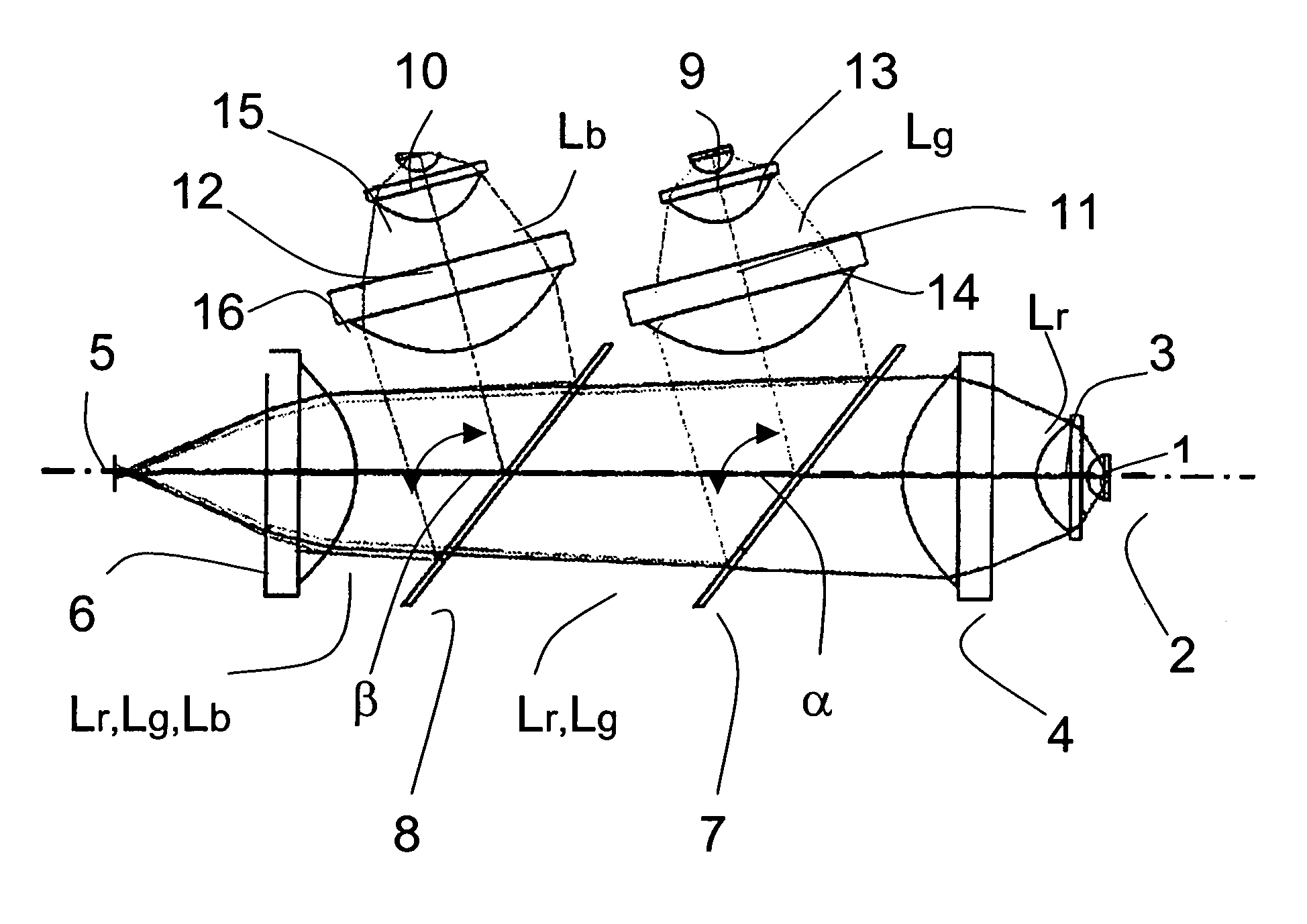
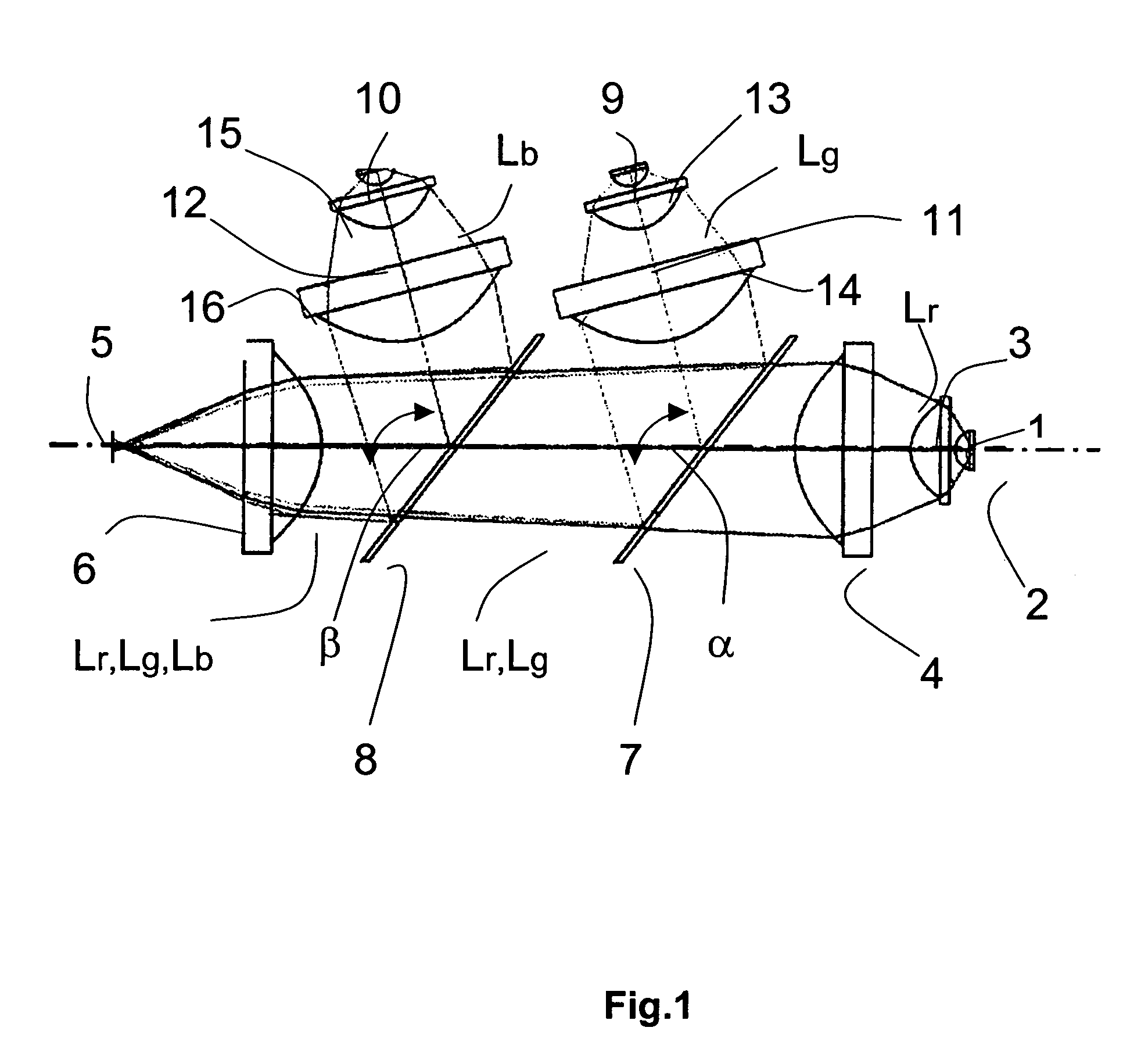
[0026]The corresponding figure shows a red LED 1, whose optical axis lies on the optical axis 2 of the illumination module, wherein the light beams Lr are collimated through convergent lenses 3 and 4. For the purpose of focusing the light beams Lr onto the light entry surfaces 5 of a light-mixing rod, which is not depicted in detail, an additional convergent lens 6 is located in the beam path. The convergent lenses 3, 4 and 6 are broadband lumenized plastic lenses, which each have at least one aspheric surface and are arranged on the optical axis 2 in such a way that the aspheric surfaces of the convergent lenses 3 and 4 are oriented toward the light entry surface 5 and the aspheric surface of the convergent lens 6 is oriented toward the LED 1.

[0027]For the purpose of laterally inputting the colors green and blue on the optical axis 2, two dichroic filt...


PUM


Abstract

The invention relates to an illumination module for color display, preferably for use in data or video projectors as well as rear projection television sets, in which the light from at least three luminescent diodes (LEDs) or LED arrays of the base colors red, green and blue is collimated at a point provided for connection to a display unit and ranged on an optical axis of the illumination module. An LED or an LED array of a base color with a beam path (Lr) oriented in the direction of the display unit is arranged on the optical axis of the illumination module. For the purpose of color mixing, the LEDs and LED arrays of the other base colors are attached in such a way tat their beam paths (Lg, Lb) are laterally input in sequence under input angles (α, β) of <90 degrees into the beam path (Lr) of the first base color.

Description

FIELD OF THE INVENTION[0001]The invention relates to an illumination module for color display, preferably for use in data or video projectors as well as rear projection television sets, in which the light from at least three luminescent diodes (LEDs) or LED arrays of the base colors red, green and blue is focused at a point provided for connection to a display unit and arranged on an optical axis of the illumination module.BACKGROUND OF THE INVENTION[0002]Currently, only high-pressure lamps are used as illumination modules for “optical engines” of data and video projectors, for projection monitors, as well as television sets these lamps emit a continuous spectrum in both visible light and the adjacent ranges (UV, IR). However, only narrow wavelength ranges of the colors red, green and blue are needed to produce an image. For sequential coloration, these colors are utilized individually and sequentially, with the use of a color wheel. The wavelengths not needed in this process are fi...

Claims


Application Information

Patent Timeline
Patent Type & Authority Patents(United States)
IPC IPC(8): G02B27/10G02B27/14G03B21/00F21V7/04G02B19/00G02B27/18G03B21/28H04N5/74H04N9/30H04N9/31
CPCG02B27/102G02B27/1073G02B27/145H04N9/315G02B19/0066G02B19/0028
Inventor LEITEL, ARMINWALDHAUSL, RALFSCHREIBER, PETERZEITNER, UWE DETLEF
Owner SYPRO OPTICS
Why Eureka
Try Eureka