Magnetic resonance imaging system including a transpolar fixture

Active Publication Date: 2007-07-03
FONAR
View PDF33 Cites 22 Cited by
  • Summary
  • Abstract
  • Description
  • Claims
  • Application Information

AI Technical Summary

Benefits of technology

[0010]In particularly preferred arrangements, the first and second pads are arranged to bear on the pole faces and frictionally engage the pole faces. This allows the fixture to be positioned anywhere on the pole faces, and in any position relative to the patient bed. Moreover, the preferred fixtures according to this aspect of the invention do not require modifications to the magnetic resonance imaging apparatus or the patient support. Most preferably, the fixture is substantially in the form of an elongated rod when the p

Problems solved by technology

Moreover, MRI allows visualization of tissues which are difficult or impossible to depict using other techniques.
However, magnetic resonance imaging procedures have suffered from significant limitations.
None of these systems have been widely adopted.
For example, a standing patient's lo

Method used


Image

  • Magnetic resonance imaging system including a transpolar fixture
  • Magnetic resonance imaging system including a transpolar fixture
  • Magnetic resonance imaging system including a transpolar fixture

Examples


Example

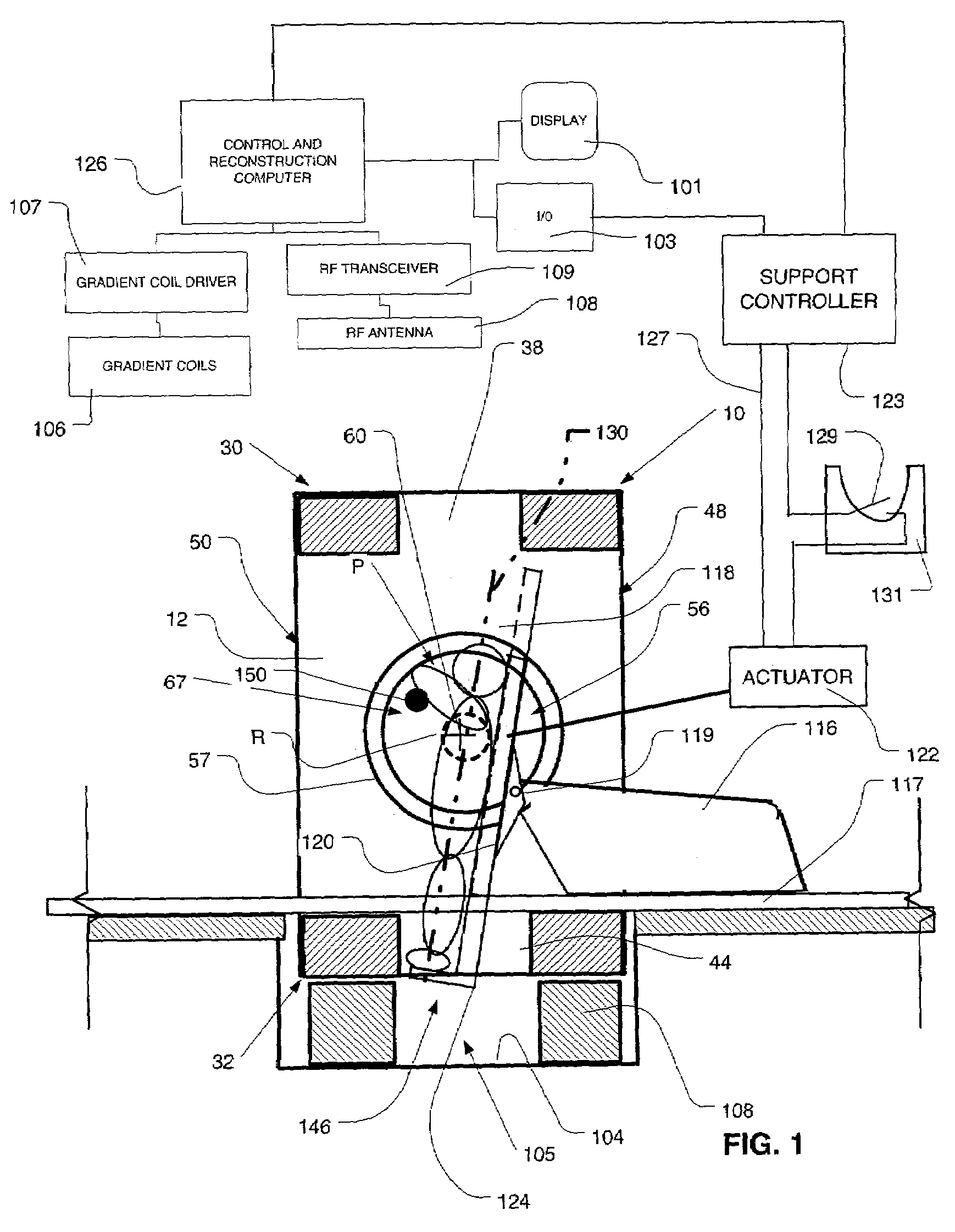
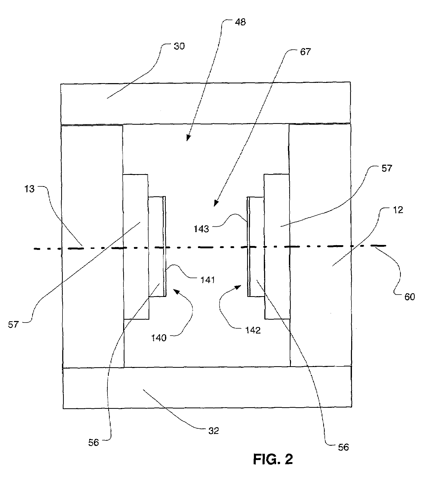
[0021]Apparatus according to one embodiment of the present invention includes a ferromagnetic frame 10. As described in greater detail in the '946 application, the frame 10 is generally box-like and includes a top flux return member 30 defining the top wall of the box, a bottom flux return member 32 defining the bottom wall of the box and a pair of generally vertical side walls 12 and 13 (FIG. 2) defining the sides of the box, one such side wall 12 being visible in FIG. 1. The box-like structure has large patient entry openings 48 and 50 (FIG. 1) at front and back sides of the box, i.e., the vertical sides which are not occupied by side wall 12 and the opposite side wall. The top flux return member 30 defines opening 38 in the top wall of the box, whereas the bottom flux return member 32 defines an opening 44 in the bottom wall. The box-like structure is maintained above a base structure 104 so that there is a space 105 beneath the bottom of the flux return member communicating with...


PUM


Abstract

A magnetic resonance imaging system is provided with a fixture which can be mounted to the static field magnet within the patient-receiving space of the magnet. The fixture can support and stabilize the patient.

Description

BACKGROUND OF THE INVENTION[0001]The present invention relates to imaging techniques and apparatus for performing such techniques, and more specifically to techniques and apparatuses for assisting patient positioning while performing such imaging techniques are performed.[0002]In magnetic resonance imaging (“MRI”), a strong, uniform magnetic field is applied to the region of the patient to be imaged. Radio frequency (“RF”) energy is applied to this region of the patient by a transmitter and antenna. The RF energy excites atomic nuclei within the patient's tissues. The excited nuclei spin at a rate dependent upon the magnetic field. As they spin, they emit faint RF signals, referred to herein as magnetic resonance signals. By applying small magnetic field gradients so that the magnitude of the magnetic field varies with location within the patient's body, the magnetic resonance phenomenon can be limited to only a particular region or “slice” of the patient's body, so that all of the ...

Claims


Application Information

Patent Timeline
IPC IPC(8): A61B5/055
CPCA61B5/055G01R33/307G01R33/3806
Inventor GREEN, CHARLES A.WAHL, WILLIAM H.CINOGLU, ARTONICKEL, KEITHGELBIEN, MARK
Owner FONAR
Why Eureka
Try Eureka