Refrigerator

a technology for refrigerators and freezers, applied in the field of refrigerators, can solve the problems of reducing the interior volume of refrigerators and the inconvenient use of ice makers in the freezing chamber of top-mounted refrigerators for short peopl

Active Publication Date: 2007-07-10
LG ELECTRONICS INC
View PDF13 Cites 18 Cited by
  • Summary
  • Abstract
  • Description
  • Claims
  • Application Information

AI Technical Summary

Benefits of technology

[0014]An object of the present invention is to provide a refrigerator, in which an ice machine is installed inside a chilling chamber door, such that short persons can easily take out ice from the refrigerator.
[0016]A further another object of the present invention is to provide a refrigerator, in which an ice machine is installed inside a chilling chamber door and a cold air circulation passage is constructed to supply a cold air sufficiently to the ice machine, such that the ice machine can have the same performance as when it is installed in a freezing chamber.

Problems solved by technology

However, the ice maker of the top mount refrigerator is accommodated in the freezing chamber, such that there is no sufficient room in the freezing chamber for other components and the user, thereby decreasing available interior volume of the refrigerator.
Further, the ice maker in the freezing chamber of the top mount refrigerator is not convenient for short persons, for example, children to take ice out of the ice maker (ice bank).
Sometimes, the short persons have to use a chair or the like to take out the ice and this may causes an accident.

Method used


Image

  • Refrigerator
  • Refrigerator
  • Refrigerator

Examples


first embodiment

[0038][First Embodiment]

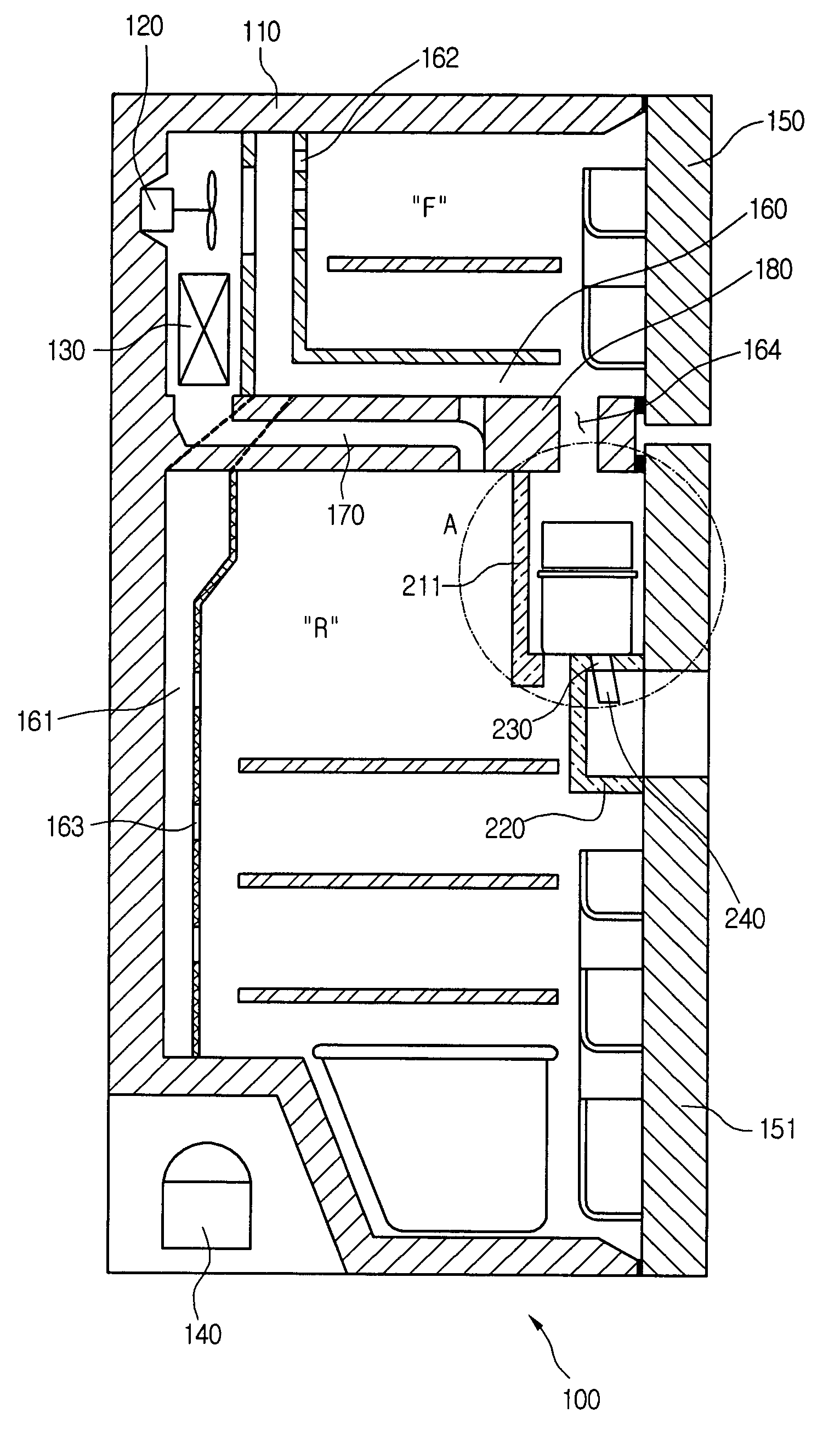
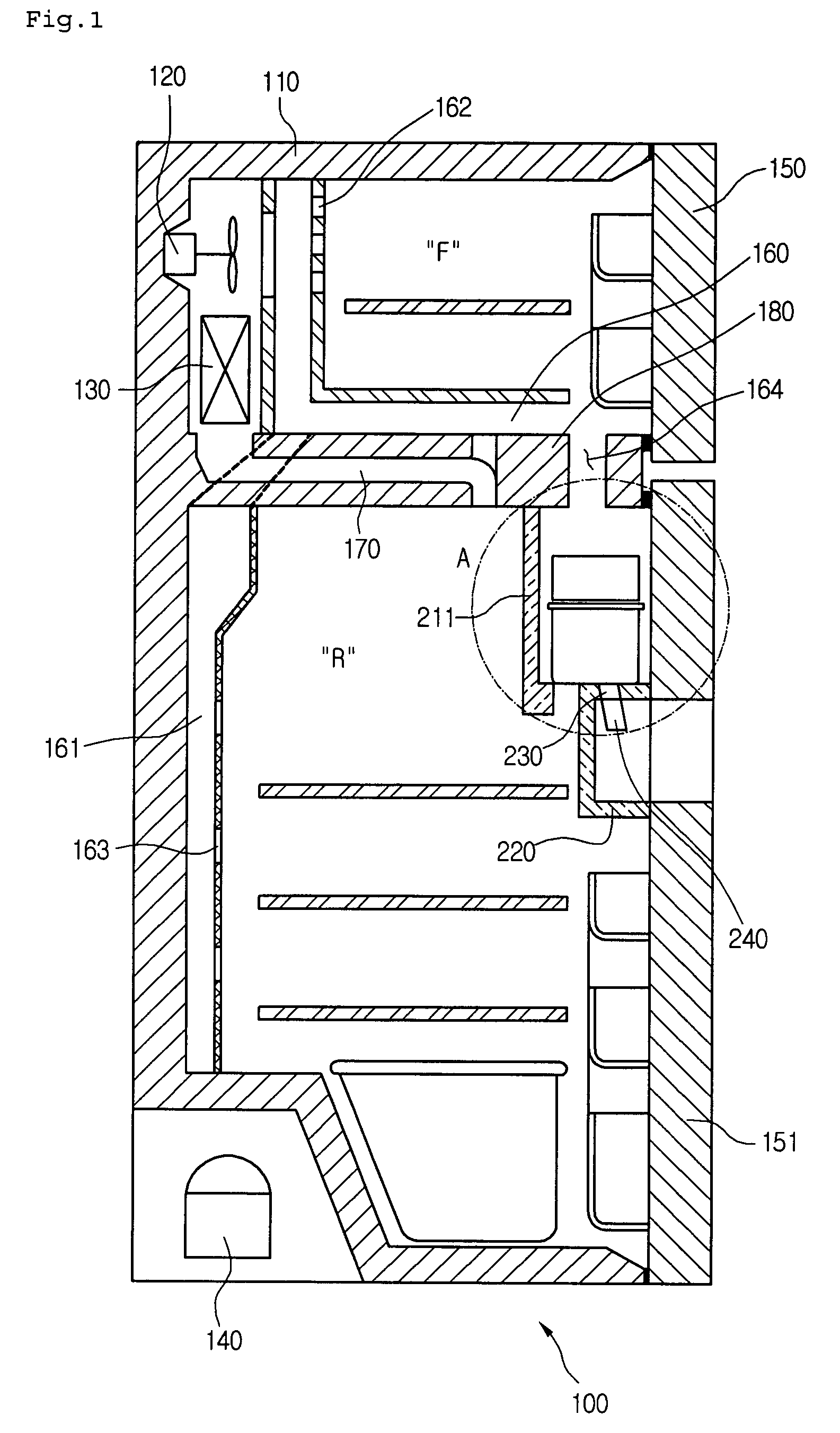
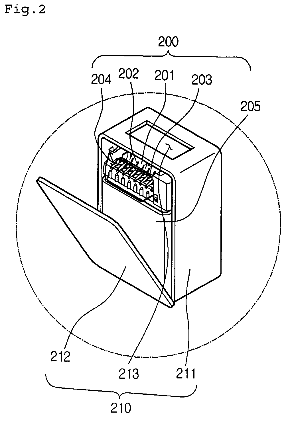
[0039]FIG. 1 is a sectional view showing an air circulation structure of a refrigerator according to a first embodiment of the present invention, and FIG. 2 is an enlarged perspective view of an ice machine depicted at portion “A” in FIG. 1.

[0040]Referring to FIGS. 1 and 2, a refrigerator 100 includes a refrigerator body 110, a freezing chamber door 150, a chilling chamber door 151, a blower fan 120, an evaporator 130, a freezing air duct 160, and a chilling air duct 161. The refrigerator body 110 forms the exterior wall and the frame of the refrigerator 100. The freezing chamber door 150 is hinged to a front upper portion of the refrigerator body 110 for opening and closing a freezing chamber (F), and the chilling chamber door 151 is hinged to a front lower portion of the refrigerator body 110 for opening and closing a chilling chamber (R). The blower fan 120 is installed at a rear portion of the refrigerator body 110 to blow a cold air to the freezing chamb...

second embodiment

[0054][Second Embodiment]

[0055]FIG. 4 is a sectional view showing an air circulation structure of a refrigerator according to a second embodiment of the present invention, and FIG. 5 is a sectional view showing an air circulation in the refrigerator depicted in FIG. 4.

[0056]Referring to FIGS. 4 and 5, a refrigerator 100 includes a freezing air duct 160, a chilling air duct 161, an inlet duct 165, an outlet duct 166, and a cold air return duct 170. A cold air blown by a blower fan 120 passes along the freezing air duct 160. The chilling air duct 161 is branched off from the freezing air duct 160 and connected to a chilling chamber (R). The inlet duct 165 is formed through a barrier 180 to connect an end of the freezing air duct 160 to an ice-making chamber 210 (refer to FIG. 2). The outlet duct 166 is formed through the barrier 180 in a vertical direction to allow a cold air circulated in the ice-making chamber 210 to enter a freezing chamber (F). The cold air return duct 170 is form...

third embodiment

[0061][Third Embodiment]

[0062]FIG. 6 is a perspective view showing an air circulation structure of a refrigerator according to a third embodiment of the present invention, and FIG. 7 is a sectional view showing an air circulation in the refrigerator depicted in FIG. 6.

[0063]Referring to FIGS. 6 and 7, a refrigerator 100 includes a barrier 180, a freezing air duct 260, a cold air return duct 270, and a chilling air duct 161. The barrier 180 divides the inner space of the refrigerator 100 into upper and lower chambers, a freezing chamber (F) and a chilling chamber (R). The freezing air duct 260 is extended through the barrier 180 and connected to a top of an insulating case 211 of an ice-making chamber 210 (refer to FIG. 2). The cold air return duct 270 is formed through the barrier 180 to allow a cold air in the ice-making chamber 210 to go back to an evaporator 130. The chilling air duct 161 allows a cold air blown by a blower fan 120 to flow toward the chilling chamber (R).

[0064]Th...


PUM


Abstract

There is provided a refrigerator. In the refrigerator, a blower fan is installed in a refrigerant body to blow a cold air, a barrier partitions an inner space of the refrigerator body into a freezing chamber and a chilling chamber, an ice machine is installed in the chilling chamber, a freezing air duct is connected with the ice machine for passing the cold air blown by the blower fan, a chilling air duct is connected with the chilling chamber for passing the cold air blown by the blower fan, and a cold air return duct is provided to pass the cold air discharged from the ice machine toward an evaporator where the cold air is cooled by exchanging heat with a refrigerant.

Description

BACKGROUND OF THE INVENTION[0001]1. Field of the Invention[0002]The present invention is related to a refrigerator, and more particularly, to a top mount refrigerator in which an ice machine is installed inside a chilling chamber door, and a cold air circulation passage is defined to supply cold air for the ice machine to freeze water in the ice machine quickly.[0003]2. Description of the Related Art[0004]A refrigerator is an electrical appliance for cooling or freezing food to preserve the food. The refrigerator carries out a refrigeration cycle using a compressor, a condenser, an expansion valve, and an evaporator to produce a cold air to store the food. The refrigerator can be classified into a top mount refrigerator in which a freezing chamber and a chilling chamber are partitioned up and down, a bottom freezer refrigerator in which a freezing chamber and a chilling chamber are partitioned down and up, and a side-by-side refrigerator in which a freezing chamber and a chilling ch...

Claims


Application Information

Patent Timeline
Patent Type & Authority Patents(United States)
IPC IPC(8): F25C1/12F25C1/00F25C5/00F25D17/08F25D11/02F25D17/06F25D23/12F25D25/00
CPCF25D17/065F25D23/126F25C2400/10F25D23/04F25D2317/062F25D2317/0653F25D2317/0666F25D2317/067F25D2400/04H04M1/026H05K9/0084
Inventor LEE, MYUNG RYULCHUNG, SUNG HOONKIM, SEONG JAESEO, CHANG HO
Owner LG ELECTRONICS INC
Why Eureka
Try Eureka