Method and apparatus for determining the gas flow rate of a gas-liquid mixture

a gas-liquid mixture and flow rate technology, which is applied in the direction of indirect mass flowmeters, instruments, measurement devices, etc., can solve the problems of difficult to reliably perform, equipment is bulky and expensive, and the accuracy of calculations starts to degrade, so as to improve the mixing

Active Publication Date: 2007-07-10
SCHLUMBERGER TECH CORP
View PDF7 Cites 25 Cited by
  • Summary
  • Abstract
  • Description
  • Claims
  • Application Information

AI Technical Summary

Benefits of technology

[0048]Thus by using a corrective term which comprises the estimated GVF instead of the liquid flow rate, it is possible to avoid the practical difficulties associated with tracer dilution techniques for measuring the liquid flow rate.
[0053]The flow meter may be arranged such that the flow through the meter is substantially vertical. Such an arrangement helps to avoid stratification (and thereby improves the mixing) of the gas and liquid phase in the flow meter. Particularly when a gamma-ray densitometer is used to measure the density, stratification can lead to errors in the density measurements.

Problems solved by technology

However, with conventional implementations of VenturiX™ technology the accuracy of the calculations starts to degrade as the gas volume fraction (GVF) increases above about 85% (the GVF being defined as the gas volumetric flow rate divided by the total volumetric flow rate of the gas-liquid mixture).
This can be a problem because as oil wells age the GVF increases towards 100% and as gas wells age the GVF decreases from 100%.
However, this relies on the efficient separation of the gas and liquid phases, which is difficult to perform reliably.
Furthermore the equipment tends to be bulky and expensive.
However, the differences between the correlations are small when they are used to calculate the flow rate of a wet gas.
However, tracer measurements involve practical difficulties and can be inconvenient to perform.
Moreover tracer measurements are typically non-continuous.

Method used


Image

  • Method and apparatus for determining the gas flow rate of a gas-liquid mixture
  • Method and apparatus for determining the gas flow rate of a gas-liquid mixture
  • Method and apparatus for determining the gas flow rate of a gas-liquid mixture

Examples


Embodiment Construction

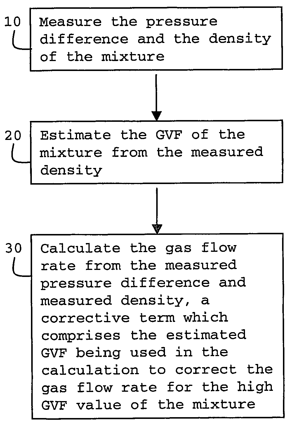
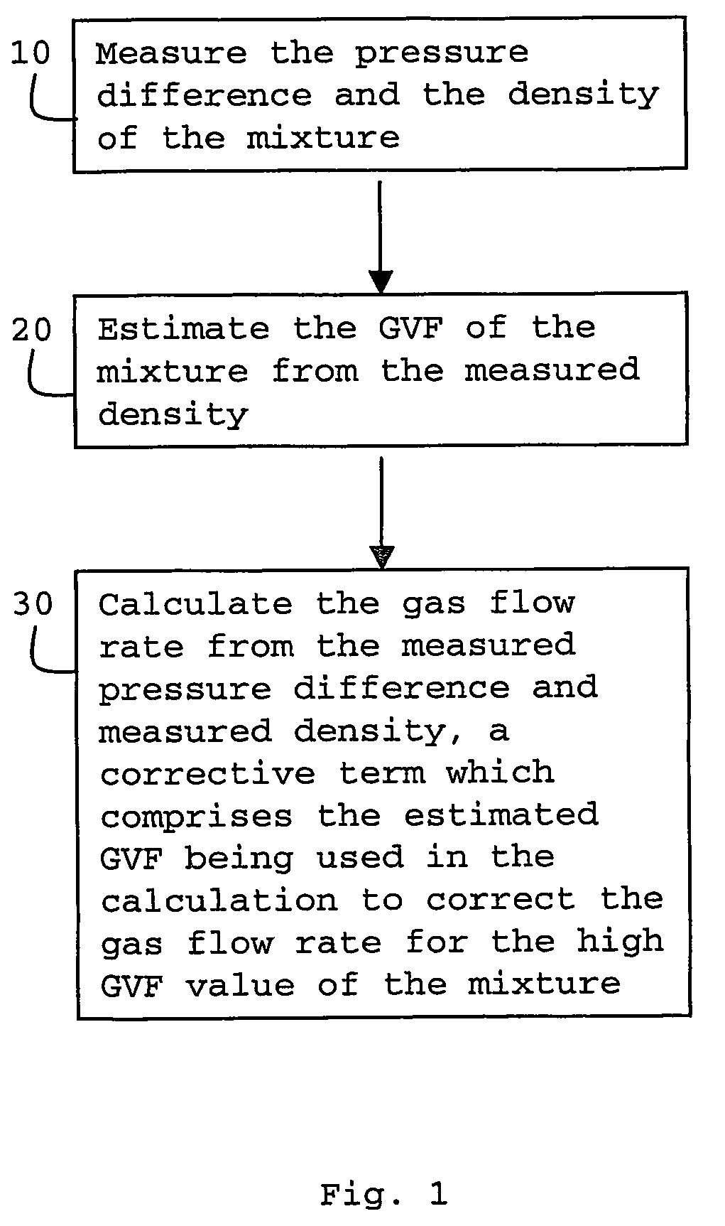
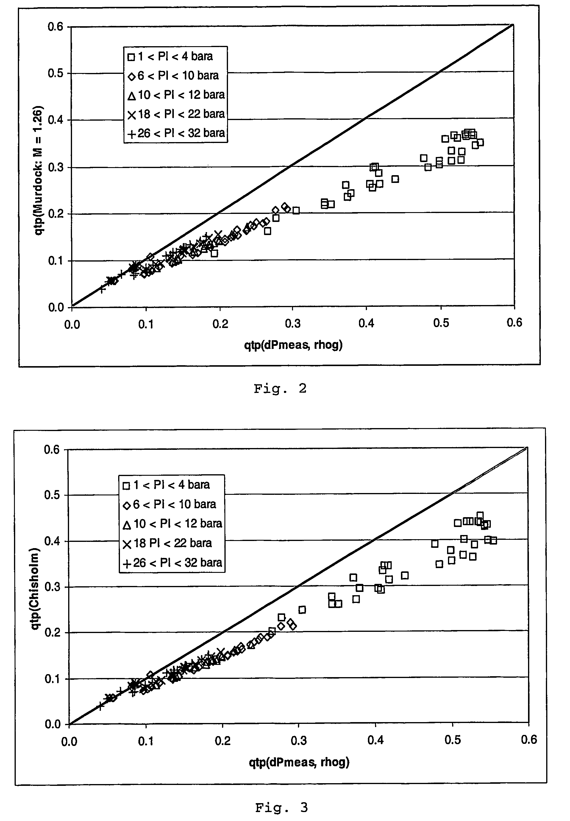
[0078]FIG. 1 is a flow chart illustrating-a method of determining the gas flow rate of a gas-liquid mixture according to the present invention. The gas-liquid mixture has a gas volume fraction (GVF) of at least 85% and is conveyed along a conduit fitted with a differential pressure flow meter and a fluid densitometer. In step 10, the pressure difference and the density of the mixture are measured. Next, in step 20, the GVF of the mixture is estimated from the measured density. Finally, in step 30, the gas flow rate is calculated from the measured pressure difference and measured density, a corrective term which comprises the estimated GVF being used in the calculation to correct the gas flow rate for the high GVF value of the mixture. For the final calculation step, the method draws on correlations such as:

qg=f(qtp, ql / qg)

discussed briefly above. Before considering further examples of the present invention, it is useful to consider examples of such correlations in more detail.

Flow R...


PUM


Abstract

A method and apparatus are provided for determining the gas flow rate of a gas-liquid mixture which has a gas volume fraction (GVF) of at least 85% and which is conveyed along a conduit. The conduit is fitted with a differential pressure flow meter and a fluid densitometer. The method comprises: measuring the pressure difference across the differential pressure flow meter and measuring the density of the mixture using the densitometer; estimating the GVF of the mixture from the measured density; and calculating the gas flow rate from the measured pressure difference and measured density. A corrective term which comprises the estimated GVF is used in the calculation to correct the gas flow rate for the high GVF value of the mixture.

Description

FIELD OF THE INVENTION[0001]The present invention relates to a method and apparatus for determining the gas flow rate of a gas-liquid mixture, and in particular a gas-liquid mixture having a gas volume fraction of at least 85%.BACKGROUND OF THE INVENTION[0002]The determination of gas and liquid flow rates in gas-liquid mixtures are important measurements in the oil and gas industry.[0003]An example of an apparatus for measuring such flow rates is Schlumberger's PhaseTester™ VenturiX™ system (see e.g. I. Atkinson, M. Berard, B-V Hanssen, G. Ségéral, 17th International North Sea Flow Measurement Workshop, Oslo, Norway 25-28 Oct. 1999 “New Generation Multiphase Flowmeters from Schlumberger and Framo Engineering AS”; and http: / / www.slb.com / oilfield / index.cfm?id=id32270) which comprises a vertically mounted Venturi flow meter, a dual energy gamma-ray hold up measuring device and associated processors. This system successfully allows the simultaneous calculation of gas, water and oil volu...

Claims


Application Information

Patent Timeline
Patent Type & Authority Patents(United States)
IPC IPC(8): G01F1/44G01FG01F1/74G01F1/88
CPCG01F1/44G01F1/74G01F1/88
Inventor ATKINSON, DAVID IAN HEATON
Owner SCHLUMBERGER TECH CORP
Why Eureka
Try Eureka