Personal lift device

a technology of personal lifts and lifts, which is applied in the field of personal lifts, can solve the problems of insufficient strength of the attendant to help the patient move, the patient may be too heavy to lift, and the patient may be difficult to get up, go to the bathroom and have a bath, etc., and achieves the effect of lowering the patient, and reducing the work required to li

Inactive Publication Date: 2007-07-10
HANDICARE CANADA LTD
View PDF27 Cites 61 Cited by
  • Summary
  • Abstract
  • Description
  • Claims
  • Application Information

AI Technical Summary

Benefits of technology

[0006]According to the present invention a more efficient drive train can be used to reduce the work required to lift and lower patients. A more efficient drive train will result in either a smaller motor being required, or more lifting power being available for a motor of the same size. Quite simply the present invention comprehends having more of the energy of the electrical motor go into the lifting and lowering rather than simply being used to overcome the friction inherent in an inefficient gear train.
[0008]Another aspect of the present invention is to provide a one-way clutch in the drive train to permit the drive train to turn freely as the motor is being used to raise the patient, which in turn lowers the work done by the motor in overcoming the friction during lifting. Most preferably the one way clutch mechanism is installed in at least a portion of the drive train to, for example, isolate the brake from the lifting cycle to reduce the work of lifting.
[0009]According to a further aspect of the invention, a manual emergency lowering device is provided which is both effective in terms of overcoming the brake, and which is readily accessible when needed and conveniently stored out of the way when not. In particular the present invention provides an emergency lower device that may be easily used by an attendant standing on the ground, even though the lift device may be located at or near the ceiling and otherwise out of reach.

Problems solved by technology

However, often such patients may be too heavy to lift or the attendant may not have enough strength to help the patient move.
Getting up, going to the bathroom and having a bath, for example, can be difficult for such patients.
Typically such patient lift devices are provided with an electronic lift motor and with an inefficient gear train system.
While providing such gearing inefficiencies does act as a safety brake, it also increases the cost, size, and weight of the lift apparatus, since a larger electric motor is required to both lift and lower against the gear train.
As well, in the event of a malfunction due to electrical failure of the motor, the patient can be stuck suspended in mid air without any practical way of being released and lowered.

Method used


Image

  • Personal lift device
  • Personal lift device
  • Personal lift device

Examples


Embodiment Construction

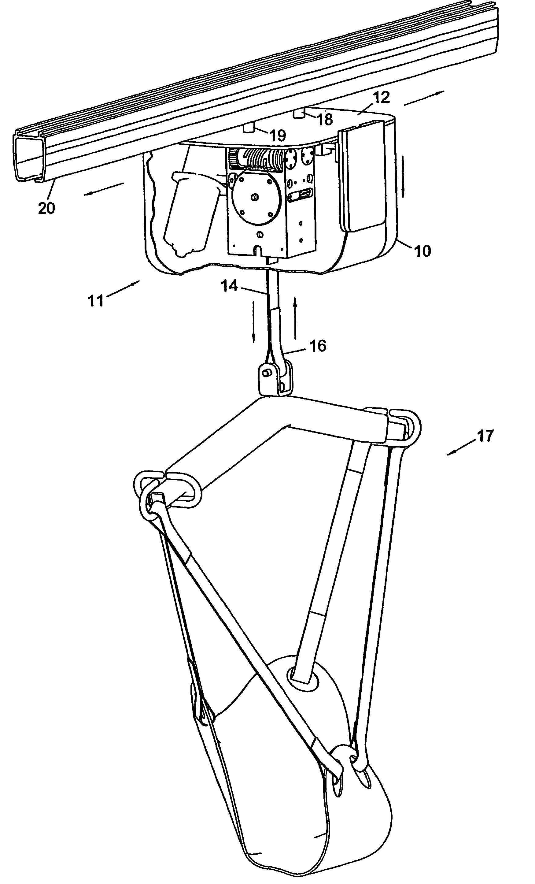
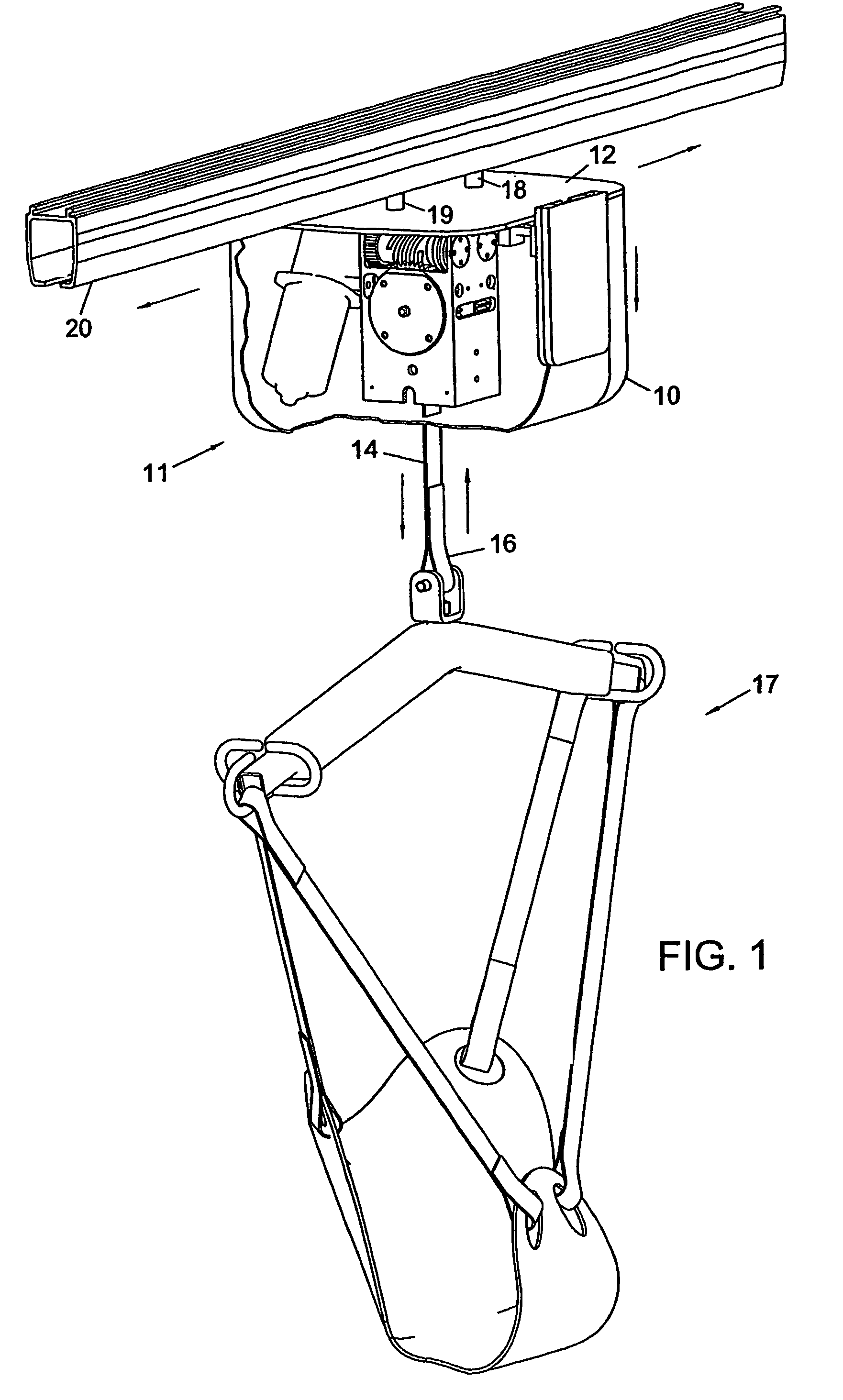
[0041]FIG. 1 shows the main elements of the present invention. In FIG. 1 there is shown a housing 10 for a personal lift device 11. The housing 10 is attached to a base plate 12. The housing 10 covers the motor and drive train (described below) of the present invention and protects the same from dirt, dust, contaminants and the like. For ease of illustration, the housing 10 is shown partially removed, but it will be understood that in the preferred form the housing 10 fully surrounds and encloses the base plate 12, as well as the inner workings of the personal lift device 11.

[0042]Shown extending from the housing 10 is a lifting and lowering strap 14 with a looped end 16. The lifting and lowering strap 14 may be attached to a patient sling or other lift device 17, and by means of operation described below, the strap 14 is raised and lowered for the purpose of lifting the patient for facilitating movement of the patient carried in the lift device 17. Also shown are upper attachment e...


PUM


Abstract

A personal lift device is disclosed having a motor having an output shaft. A gearing system is operatively connected to the output shaft for increasing torque. A strap for suspending a weight is wound onto a spool and rotating the spool extends and retracts the strap. A drive connection is made between the gearing system and the spool to permit said motor to drive said spool. A brake is associated with said spool to prevent unwanted extension of said strap from said spool, when a weight is suspended by said strap. In a preferred embodiment a clutch is provided between the brake and the drive train, and the greater the weight supported by the spool the greater the braking force. An emergency lift and lower device is also provided in the event of a failure of the motor.

Description

[0001]This application is a claims priority to International Publication Number WO 03 / 064312 A2, which has an international filing date of Jan. 27, 2003; and which claims priority to Canadian Patent Application No. 2,369,668 filed Jan. 28, 2002, and is related to Canadian Application No. 2,417,506; the entire contents of all of which are incorporated herein by reference.FIELD OF THE INVENTION[0002]This invention relates generally to the field of mobility devices, and more particularly to personal lift devices of the type that may be used to raise or lower a physically disabled person for the purpose of moving them. Most particularly, this invention relates to a form of personal lift device that can be activated to raise or lower a patient or physically disabled person.BACKGROUND OF THE INVENTION[0003]Personal lift or patient lift devices have been known and used in the past for the purpose of assisting with the mobility of otherwise immobilized patients. An attendant may help physic...

Claims


Application Information

Patent Timeline
Patent Type & Authority Patents(United States)
IPC IPC(8): B61B7/00A61G7/10B66D1/14B66D3/22
CPCA61G7/1015A61G7/1042A61G7/1051B66D1/14B66D3/22A61G7/1061A61G2200/34
Inventor CHEPURNY, MARKMOLNAR, GORDON J.WILSON, MICHAEL F.
Owner HANDICARE CANADA LTD
Why Eureka
Try Eureka