Tube joint

a technology of tube joints and joints, applied in the direction of hose connections, pipe couplings, couplings, etc., can solve the problems of excessive load applied to the diametrally expanded portion of tubes, and achieve the effect of preventing the tube member from being disengaged from the joint body

Active Publication Date: 2007-07-10
SMC CORP
View PDF44 Cites 32 Cited by
  • Summary
  • Abstract
  • Description
  • Claims
  • Application Information

AI Technical Summary

Benefits of technology

[0008]A general object of the present invention is to provide a tube joint which makes it possible to reliably prevent a tube member from being disengaged from a joint body.
[0009]A principal object of the present invention is to provide a tube joint which makes it possible to secure an appropriate screwing amount of a nut member on a joint body.
[0011]According to the present invention, the outer circumferential surface of the tube member is fastened by the fastening mechanism which is pressed radially inwardly by the inner wall surface of the nut member. Therefore, even when any force is exerted in a pull-out direction of the tube member, the tube member is prevented from disengagement from the joint body.
[0016]The annular projection is plastically deformable so that the nut member is capable of being further screwed from where the annular projection abuts against the abutment surface of the joint body. Accordingly, even when the tightening torque of the nut member for the joint body is decreased, it is possible to retain the tightening torque to be constant.
[0017]Further, the nut member is formed with a plug hole for inserting the tube member thereinto, and an edge section is provided on the inner wall surface of the nut member in the vicinity of an end of the plug hole, the edge section bites into the outer circumferential surface of the tube member. Accordingly, the tube member is fastened more reliably.
[0018]It is preferable that a tapered surface is formed at the end of the joint body, the tapered surface is diametrally expanded gradually in a direction in which the tube member is inserted, and a projection is formed circumferentially on the tapered surface, corresponding to the edge section of the nut member. It is preferable that a projection is formed circumferentially corresponding to the fastening pawls formed on the collet sections, the projection is provided on an outer circumferential surface at an end of the joint body. When each of the projections is formed at the portion of the nut member opposed to the edge section or the portion opposed to the fastening pawl of the collet section, the surface pressure is increased, and it is possible to improve the sealing effect.

Problems solved by technology

Therefore, excessive load may be applied to the diametrally expanded portion of the tube 1.

Method used


Image

  • Tube joint
  • Tube joint
  • Tube joint

Examples


Embodiment Construction

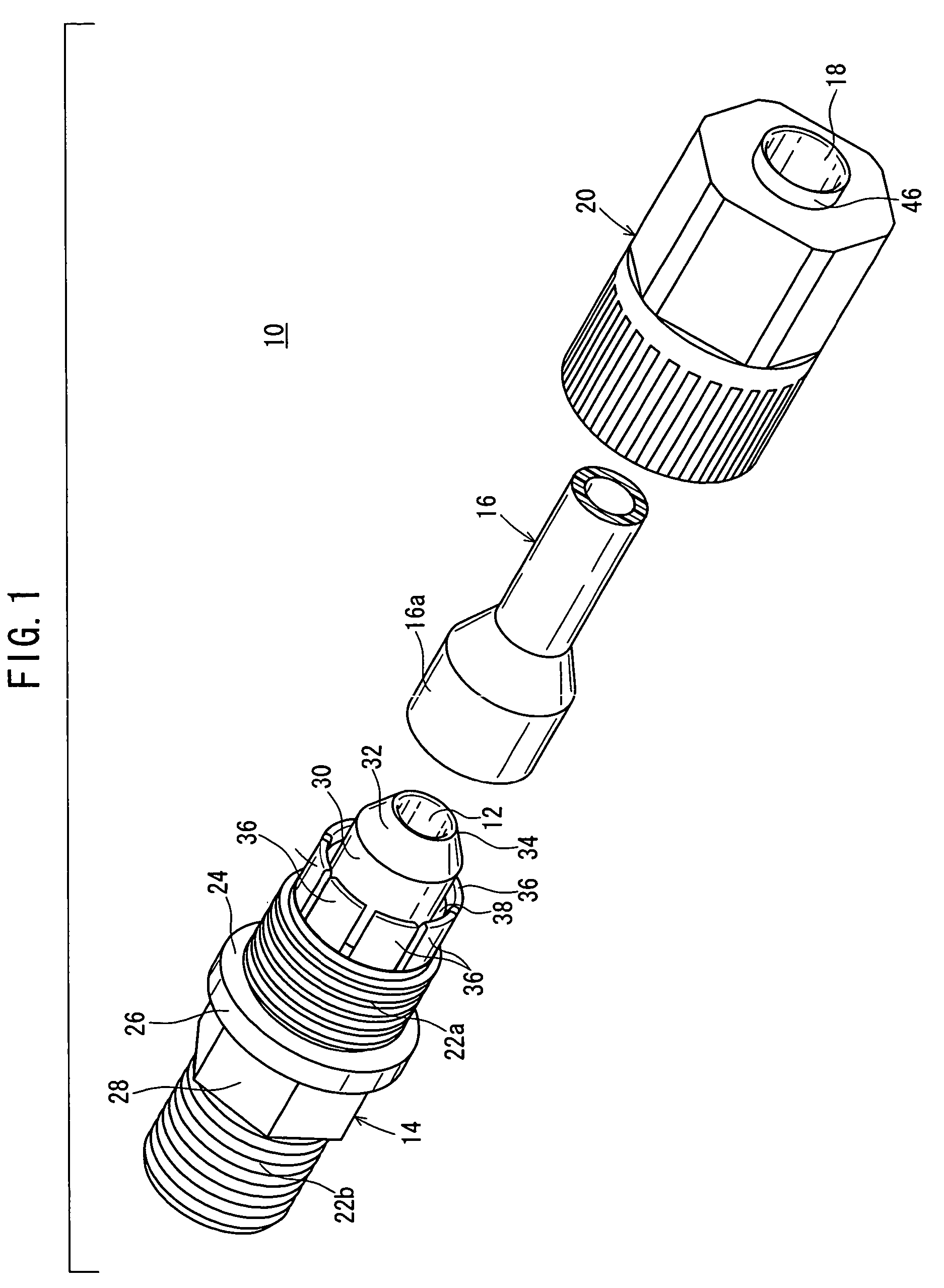
[0029]With reference to FIG. 1, reference numeral 10 indicates a tube joint according to an embodiment of the present invention.

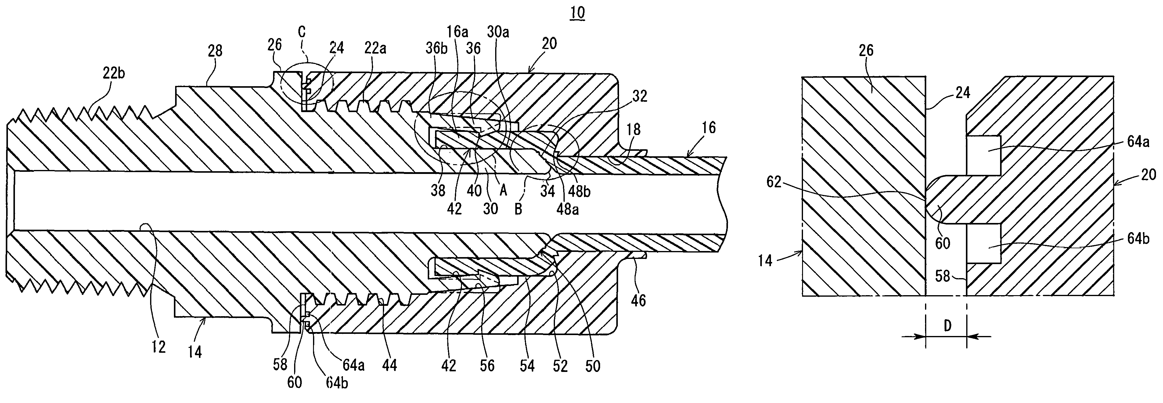
[0030]The tube joint 10 comprises a substantially cylindrical joint body 14 which has a through-hole 12 as a fluid passage formed linearly in the axial direction, and a nut member 20 which has a plug hole 18 having a circular cross section for inserting a tube (tube member) 16 thereinto and which is fitted to the joint body 14 to hold the tube 16 thereby. Each of the joint body 14 and the nut member 20 is formed of a resin material.

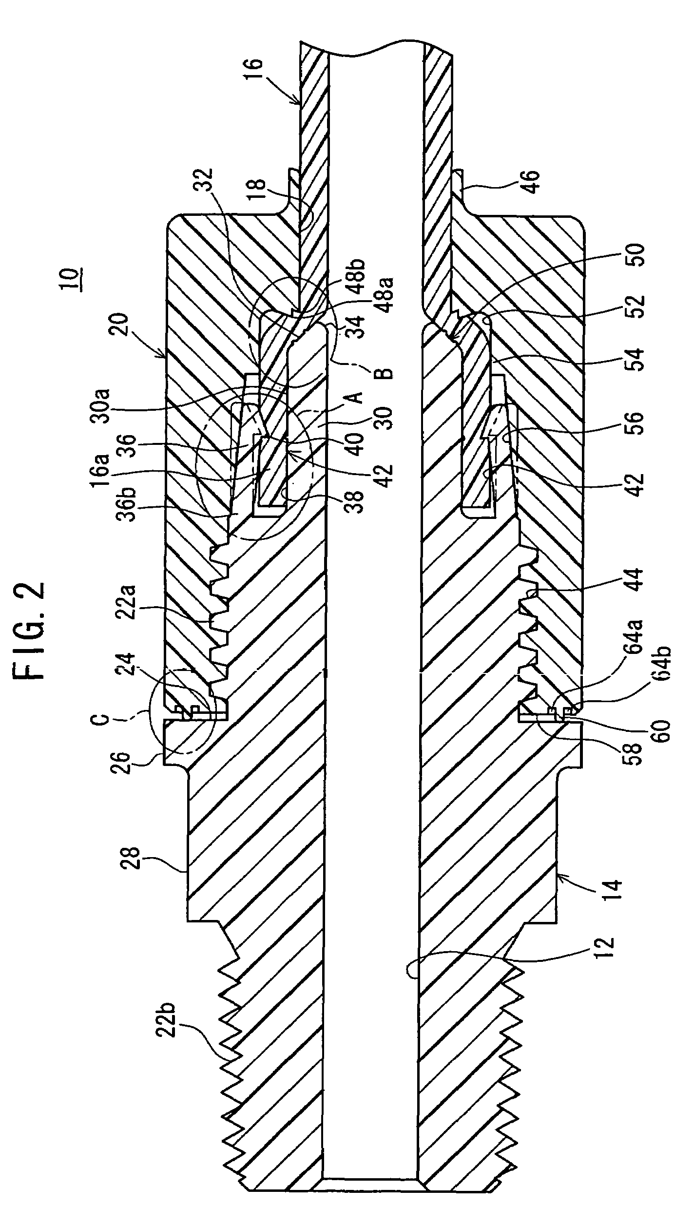
[0031]As shown in FIG. 2, the joint body 14 is provided with a first male screw section (first screw section) 22a which has a screw thread having a substantially trapezoidal cross section formed on the outer circumferential surface in the vicinity of one end, and a second male screw section 22b which has a screw thread having a sawteeth-shaped cross section formed on the outer circumferential surface at the other end. An annular ...


PUM

PropertyMeasurementUnit
inner diametersaaaaaaaaaa
corrosion resistanceaaaaaaaaaa
chemical resistanceaaaaaaaaaa

Abstract

A tube joint comprises a nut member which connects a tube to a joint body, collet sections which fasten the tube by fastening pawls for being pressed radially inwardly by a pressing section of the nut member to bite into an outer circumferential surface of a diametrally expanded section of the tube, and an annular projection which abuts against an annular step of the joint body and which regulates a screwing amount of the nut member on the joint body.

Description

BACKGROUND OF THE INVENTION[0001]1. Field of the Invention[0002]The present invention relates to a tube joint which makes it possible to connect a tube member to a fluid-operated apparatus in a liquid-tight manner or in an airtight manner.[0003]2. Description of the Related Art[0004]When a semiconductor chip is produced, a tube joint made of resin such as fluororesin has been hitherto used in a production line or the like in which a pure water washing solution or other chemical solutions or the like are used, in view of the cleanness, the corrosion resistance, and the chemical resistance.[0005]Such a tube joint is disclosed, for example, in Japanese Laid-Open Patent Publication No. 11-182751. That is, as shown in FIG. 9, a diametrally expanded end 2 of a tube 1 is fitted into a ring groove 6 of a main joint body 5 penetratingly through a plug hole 4 of a nut member 3. A female screw section 8 on the inner circumferential surface of the nut member 3 is screwed with a male screw secti...

Claims


Application Information

Patent Timeline
Patent Type & Authority Patents(United States)
IPC IPC(8): F16L33/00F16L19/02F16L19/04F16L19/06F16L19/065
CPCF16L47/04F16L19/0283F16L2201/10F16L47/041F16L19/06
Inventor FUKANO, YOSHIHIROUCHINO, TADASHI
Owner SMC CORP
Why Eureka
Try Eureka