Force sensor for vehicle brake application

a technology of force sensor and vehicle brake, which is applied in the direction of mechanical equipment, braking systems, transportation and packaging, etc., can solve the problems of little available space along the transmission path, no practical application or location for placing a force sensor has been identified in the disc brake environment, and the effect of reducing the current flow of electric resistan

Active Publication Date: 2005-05-19
ARVINMERITOR TECH
View PDF11 Cites 17 Cited by
  • Summary
  • Abstract
  • Description
  • Claims
  • Application Information

AI Technical Summary

Benefits of technology

[0007] The force sensor is preferably at a location where it is in line of a reaction force between an actuator and the brake pad. More preferably, a bearing cup that supports an eccentric pivoting shaft receives the sensor on a face opposed to a location of the bearings supported by the bearing cup. The eccentric shaft is driven by the actuator and pivots to move the bearings, to in turn actuate the disc brake. The bearing cup receives a reaction force from this force application. The reaction force is transferred to the sensor. In this manner, the sensor is able to provide a very good indication of the initiation of the force increase, which is the time when all clearance has been taken up. A second sensor may monitor movement, such as eccentric shaft rotation, to associate the point of force increase to an amount of movement.
[0008] In a most preferred embodiment, the sensor includes a force sensor of the type that receives a small electric current. An example would be a sensor from Tekscan branded as “FlexiForce” as described in U.S. Pat. No. 6,272,936. Electric resistance to the current flow decreases as the force on the sensor increases. In the most preferred embodiment, a protective cover is placed over the sensor, and a very thin “anvil” is placed between the cover and the sensor. The anvil provides the force transmission point between the cover and the sensor. The anvil limits the amount of force that can be transferred from the cover to the sensor, thus protecting the sensor.
[0009] When the brake is applied, the resistance should be relatively constant as the clearance is taken up. Once all clearance has been taken up, the brake pad begins to contact the rotor. At that point, a sharp increase in the force being applied will be sensed as a reaction force at the sensor. At this time, the resistance at the sensor will drop off sharply. The sensor sends a signal to a control for an adjustment motor. This drop off in resistance can be identified by the control as the point at which all clearance has been taken. This position, combined with other sensor information indicative of the amount of total movement of the brake will allow the control to determine an appropriate amount of adjustment.

Problems solved by technology

Typically, there is a desired amount of piston movement, and with wear on the brake pad, the pistons need to move an amount beyond this desired amount.
Thus, the mechanical adjustment mechanism changes a rest, or starting position of the pistons such that they only need to move the desired amount, even with wear on the brake pad.
However, to date, no practical application or location for placement of a force sensor has been identified in the disc brake environment.
Strain gauges, etc. have been placed along the force transmission path, however, these are not practical in the environment of the disc brake actuation assembly.
Typically, there is little available space along the transmission path.
However, this location is somewhat remote and may not provide feedback as accurately as desired.

Method used


Image

  • Force sensor for vehicle brake application
  • Force sensor for vehicle brake application
  • Force sensor for vehicle brake application

Examples


Embodiment Construction

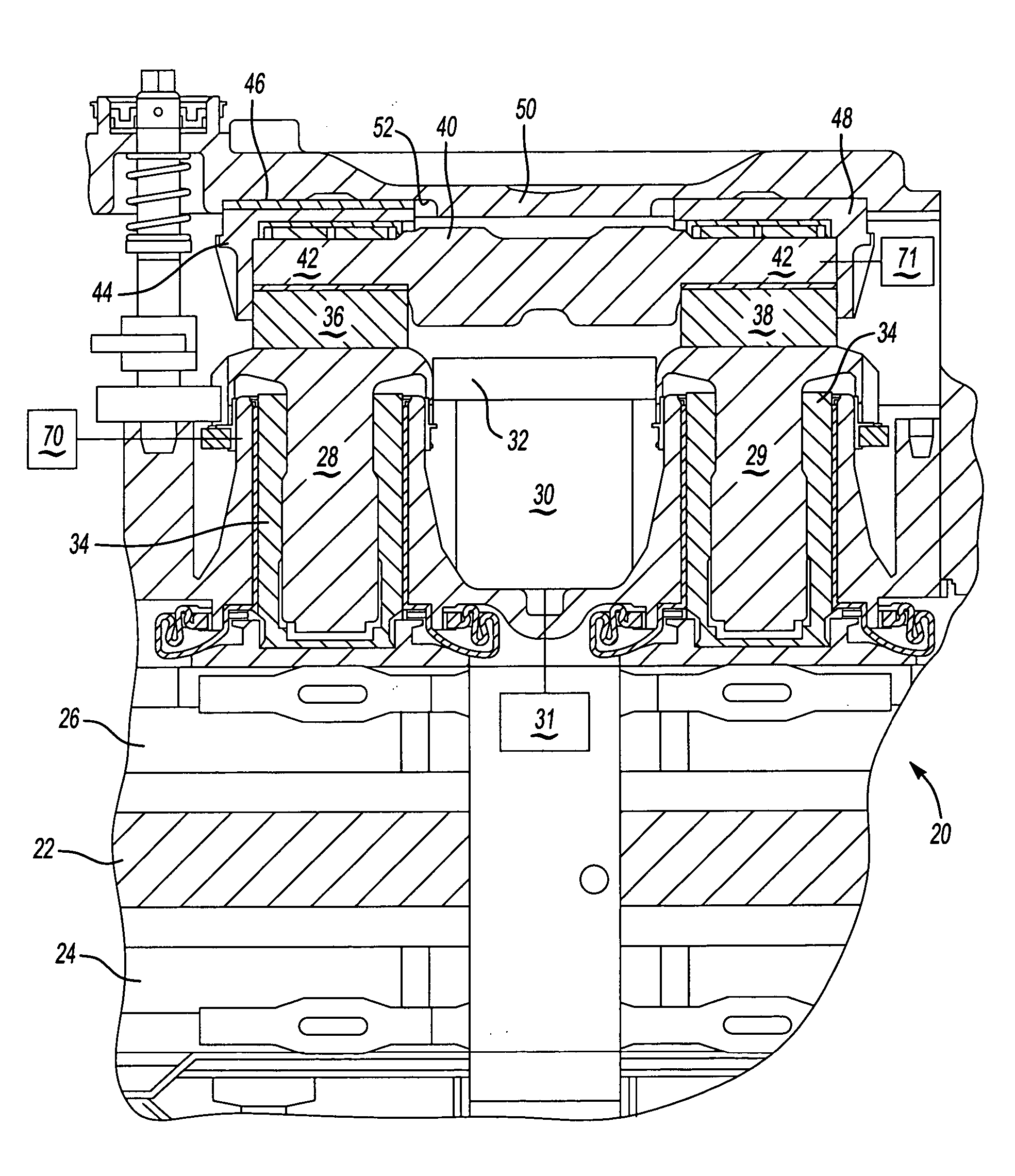
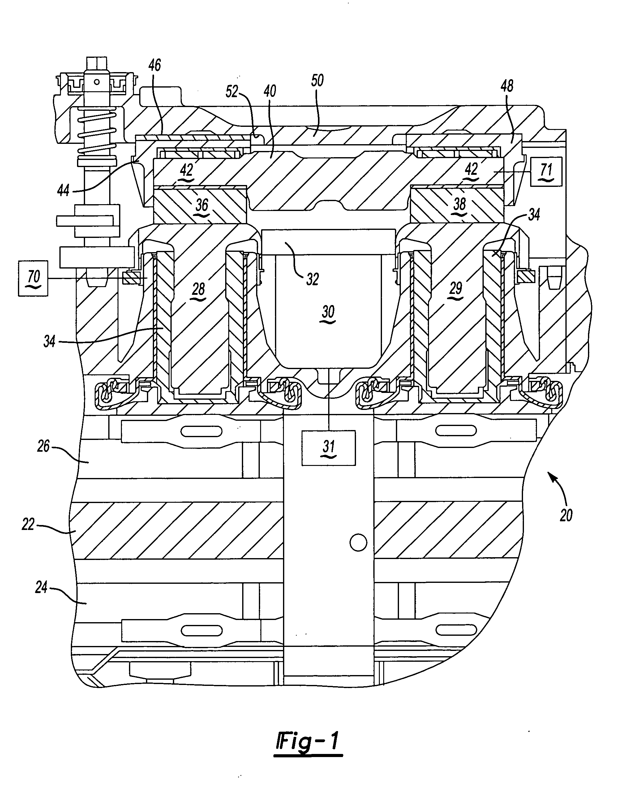
[0017] Disc brake 20 is illustrated in FIG. 1 having an actuator shaft 40, as known. A brake pad 26 is driven toward a rotor 22 that is to be braked by the disc brake 20. A pair of actuator pistons 34 drive the brake pad 26 toward rotor 22 upon control of the actuator shaft 40 as explained below. As known, an opposed brake pad 24 is also brought into contact with rotor 22.

[0018] As known, the position of the pistons 34 should be adjusted toward the item to be braked, or downwardly as shown in FIG. 1, with wear on the brake pads 24 and 26. Thus, it is known to have tappet gears 28 and 29 for providing adjustment. Historically, this adjustment has been mechanical. However, more recently, this adjustment has been provided by utilizing an electric motor. Elector motor 30 is illustrated schematically in FIG. 1 driving a gear 32 to drive tappet gears 28 and 29. Such an arrangement is shown, for example in U.S. Pat. No. 6,293,370.

[0019] As can be appreciated, pistons 34 have internally t...


PUM


Abstract

A force sensor is incorporated into a disc brake, and is operable to sense the point of force application increase during application of the disc brake. The force will increase sharply once the brake pad initially contacts the rotor. The sensor is able to determine the point of this force increase, and provide this information to a control. The control powers an electric motor for providing electric motor adjustment of the position of the piston which drives the brake pad, to compensate for wear. In a preferred embodiment, the sensor includes a protective cover with a thin anvil between the cover and the sensor. The anvil is operable to transmit the force, and limit the force applied, to protect the sensor.

Description

BACKGROUND OF THE INVENTION [0001] This application relates to a force sensor utilized in combination with an adjustment mechanism for a disc brake, wherein the force sensor provides an accurate indication of the point of brake application to a control associated with the adjustment mechanism. [0002] Disc brakes have historically included a mechanical adjustment mechanism to adjust for wear. As known, in a disc brake, a brake actuator drives a pair of pistons, and the pistons force a brake pad against a rotor, slowing rotation of the rotor. There is normal wear on the brake pad, and typically the pistons are provided with the mechanical adjustment mechanism. The mechanical adjustment mechanism includes a mechanical linkage that senses the total movement, and adjusts the pistons relative to tappet gears to take up clearance. Typically, there is a desired amount of piston movement, and with wear on the brake pad, the pistons need to move an amount beyond this desired amount. Thus, the...

Claims


Application Information

Patent Timeline
Patent Type & Authority Applications(United States)
IPC IPC(8): B60T13/66B60T13/74B60T17/22F16D55/02F16D65/14F16D65/28
CPCB60T13/741F16D65/183F16D2121/14F16D2065/386F16D2066/005F16D65/568
Inventor KRAMER, DENNIS A.
Owner ARVINMERITOR TECH
Why Eureka
Try Eureka