
Automatic directional control system for vehicle headlights

a technology of automatic directional control and headlights, which is applied in the direction of lighting support devices, instruments, lighting and heating apparatus, etc., can solve the problems of deficiency of known automatic headlight directional control systems, and the inability to adjust the directional aiming angle of headlights to account for changes in the operating conditions of vehicles

Inactive Publication Date: 2007-07-10
APAPTIVE HEADLAMP SOLUTIONS
View PDF75 Cites 26 Cited by
  • Summary
  • Abstract
  • Description
  • Claims
  • Application Information

AI Technical Summary

Benefits of technology

[0006]This invention relates to an improved structure and method for operating a directional control system for vehicle headlights that is capable of automatically altering the directional aiming angles of the headlights to account for changes in the operating conditions of the vehicle. One or more operating condition sensors may be provided that generate signals that are representative of an operating condition of the vehicle, such as road speed, steering angle, pitch, suspension height, rate of change of road speed, rate of change of steering angle, rate of change of pitch, and rate of change of suspension height of the vehicle. A controller is responsive to the sensor signal for generating an output signal. An actuator is adapted to be connected to the headlight to effect movement thereof in accordance with the output signal. The controller can include a table that relates values of sensed operating condition to values of the output signal. The controller is responsive to the sensor signal for looking up the output signal in the table.

Problems solved by technology

Although such fixed aiming angle headlight systems have and continue to function adequately, they cannot alter the directional aiming angles of the headlights to account for changes in the operating conditions of the vehicle.
However, such known automatic headlight directional control systems have been found to be deficient for various reasons.

Method used


Image

  • Automatic directional control system for vehicle headlights
  • Automatic directional control system for vehicle headlights
  • Automatic directional control system for vehicle headlights

Examples


Embodiment Construction

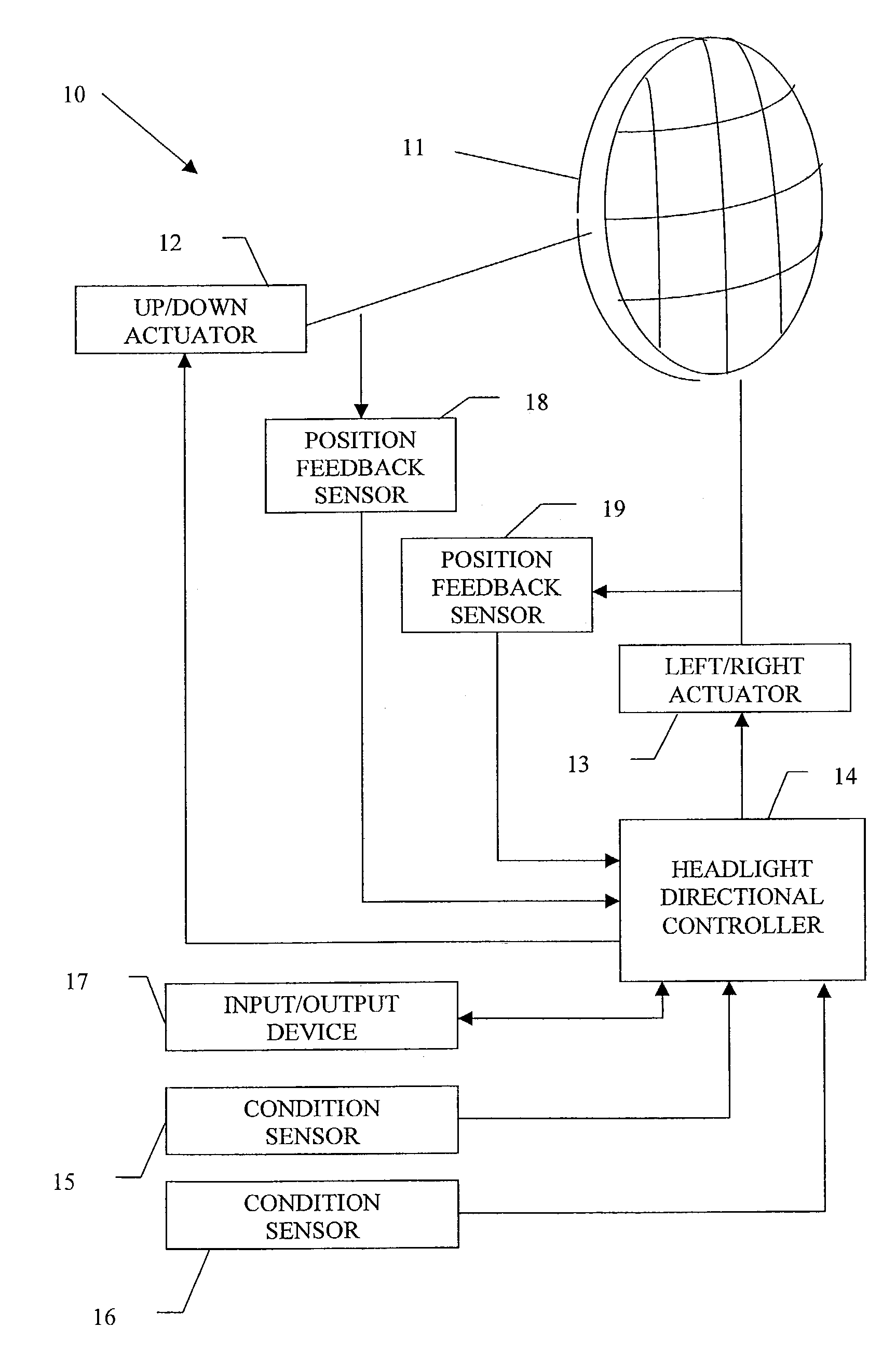
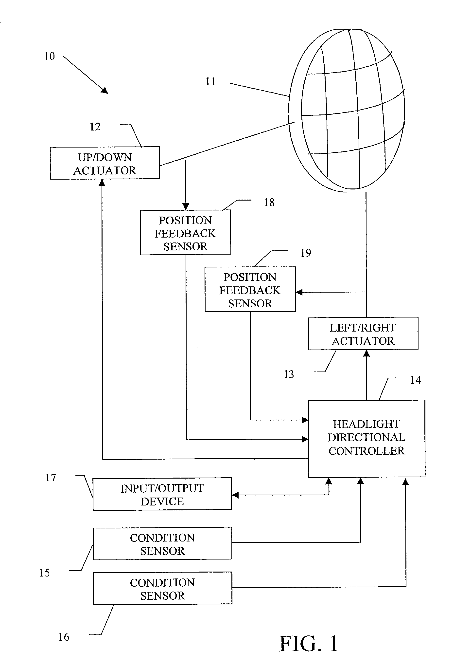
[0015]Referring now to the drawings, there is illustrated in FIG. 1 an automatic directional control system, indicated generally at 10, for a vehicle headlight 11 in accordance with this invention. The illustrated headlight 11 is, of itself, conventional in the art and is intended to be representative of any device that can be supported on any type of vehicle for the purpose of illuminating any area, such as an area in the path of movement of the vehicle. The headlight 11 is typically mounted on or near the front end of a vehicle (not shown) and is oriented in such a manner that a beam of light is projected therefrom. In a manner that is well known in the art, the headlight 11 is adapted to illuminate a portion of a dark road surface or other area in the path of movement of the vehicle to facilitate safe travel thereon.

[0016]The headlight 11 is adjustably mounted on the vehicle such that the directional orientation at which the beam of light projects therefrom can be adjusted relati...


PUM


Abstract

A structure and method for operating a directional control system for vehicle headlights that is capable of altering the directional aiming angles of the headlights to account for changes in the operating conditions of the vehicle. One or more operating condition sensors may be provided that generate signals that are representative of a condition of the vehicle, such as road speed, steering angle, pitch, suspension height, rate of change of road speed, rate of change of steering angle, rate of change of pitch, and rate of change of suspension height of the vehicle. A controller is responsive to the sensor signal for generating an output signal. An actuator is adapted to be connected to the headlight to effect movement thereof in accordance with the output signal. The controller can include a table that relates values of sensed operating condition to values of the output signal. The controller is responsive to the sensor signal for looking up the output signal in the table.

Description

CROSS REFERENCE TO RELATED APPLICATIONS[0001]This application claims the benefit of U.S. Provisional Application Nos. 60 / 335,409, filed Oct. 31, 2001; 60 / 356,703, filed Feb. 13, 2002; and 60 / 369,447, filed Apr. 2, 2002, the disclosures of which are incorporated herein by reference.BACKGROUND OF THE INVENTION[0002]This invention relates in general to headlights that are provided on vehicles for illuminating dark road surfaces or other areas in the path of movement. In particular, this invention relates to an automatic directional control system for such vehicle headlights.[0003]Virtually all land vehicles, and many other types of vehicles (such as boats and airplanes, for example), are provided with one or more headlights that are adapted to illuminate a portion of a dark road surface or other area in the path of movement of the vehicle to facilitate safe travel thereon. Typically, each headlight is mounted on or near the front end of the vehicle and is oriented in such a manner that...

Claims


Application Information

Patent Timeline
Patent Type & Authority Patents(United States)
IPC IPC(8): B60Q1/00B60R22/00B60Q1/10B60Q1/12B60Q1/18B60Q11/00
CPCB60Q1/10B60Q1/12B60Q1/18B60Q11/00G01M11/068B60Q2200/38B60Q2300/112B60Q2300/114B60Q2300/122B60Q2300/124B60Q2300/128B60Q2300/132B60Q2300/142
Inventor SMITH, JAMES E.MCDONALD, ANTHONY B.
Owner APAPTIVE HEADLAMP SOLUTIONS
Features
  • Generate Ideas
  • Intellectual Property
  • Life Sciences
  • Materials
  • Tech Scout
  • Unparalleled Data Quality
  • Higher Quality Content
  • 60% Fewer Hallucinations
Learn More