Circuit arrangement and method for operation of lamps

a technology of circuit arrangement and lamp, applied in the direction of electric variable regulation, sustainable buildings, instruments, etc., can solve the problems of not being suitable for large-scale production, affecting the operation efficiency of lamps, and not having a closed control loop for lamp parameters

Inactive Publication Date: 2007-07-10
PATENT TREUHAND GESELLSCHAFT FUR ELECTRIC GLUEHLAMPEN MBH
View PDF9 Cites 25 Cited by
  • Summary
  • Abstract
  • Description
  • Claims
  • Application Information

AI Technical Summary

Benefits of technology

[0012]One object of the present invention is to provide a circuit arrangement which provides a self-oscillating half-bridge inverter for operation of lamps, in which the oscillation frequency can be adjusted reliably.
[0029]A timer controls the stop device, via an input at which the timer feeds in a stop signal. As long as the timer is transmitting the stop signal in an off state, this prevents the electronic switches from being driven by the feedback device. A circuit arrangement according to the invention advantageously has only one stop device, which acts in the same way on both electronic switches in the half-bridge arrangement. During the on time, the timer transmits the stop signal in an on state, thus allowing the electronic switches to be driven by the feedback device.
[0036]The present invention is particularly advantageous when using bipolar transistors in the half-bridge arrangement. There are two reasons for this: firstly, bipolar transistors cost less than equivalent electronic switches such as MOSFETs or IGBTs. Secondly, a high current must be available to drive bipolar transistors. In the case of the present invention, this problem is solved by drawing the current for driving the bipolar transistors from the load circuit. Nevertheless, the circuit arrangement according to the invention allows lamp operating variables to be controlled by means of the oscillation frequency.

Problems solved by technology

One disadvantage of this circuit arrangement is due to the fact that the oscillation frequency of the half-bridge inverter is governed by the feedback device that is used and, initially, there is no capability to influence the oscillation frequency.
This is the case in particular with half-bridge inverters using bipolar transistors, since bipolar transistors are driven with high currents, which are complex to influence.
This solution has the disadvantage that the oscillation frequency depends on the magnetic characteristics of the drive transformer.
Since these can be reduced only inaccurately, this solution is not suitable for large-scale production.
Furthermore, the proposed solution does not have a closed control loop for lamp parameters such as the lamp current and lamp power.
However, once again, these documents do not disclose any control of lamp parameters such as the lamp current or lamp power.

Method used


Image

  • Circuit arrangement and method for operation of lamps
  • Circuit arrangement and method for operation of lamps
  • Circuit arrangement and method for operation of lamps

Examples


Embodiment Construction

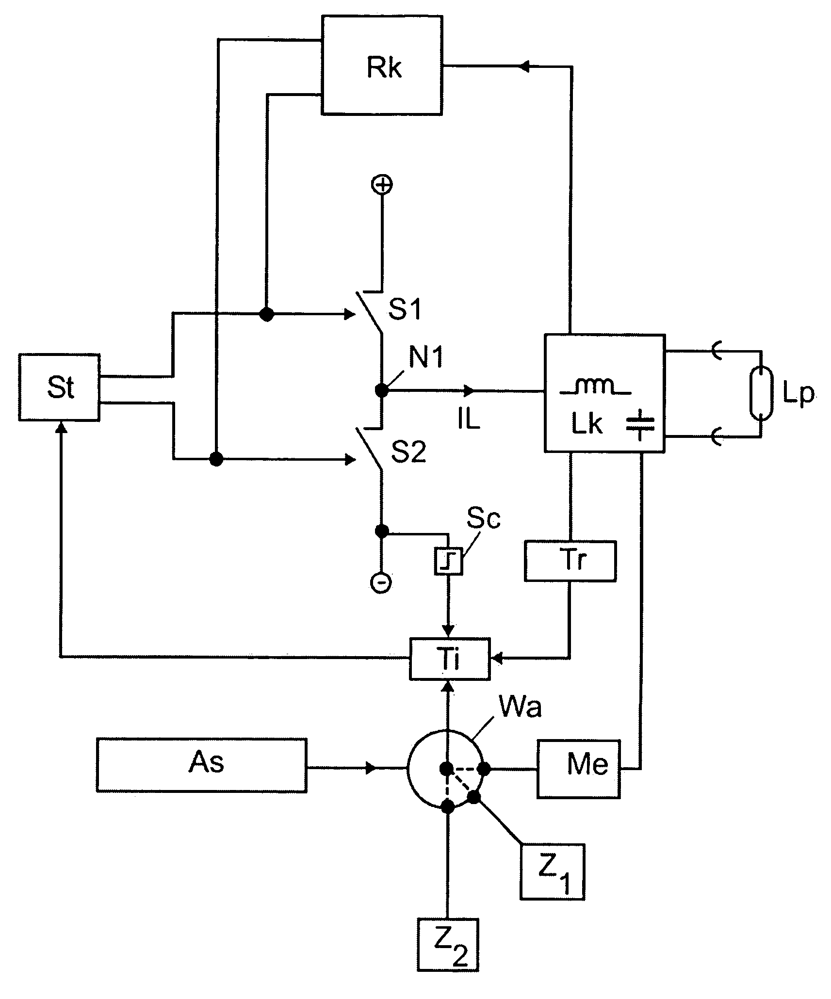
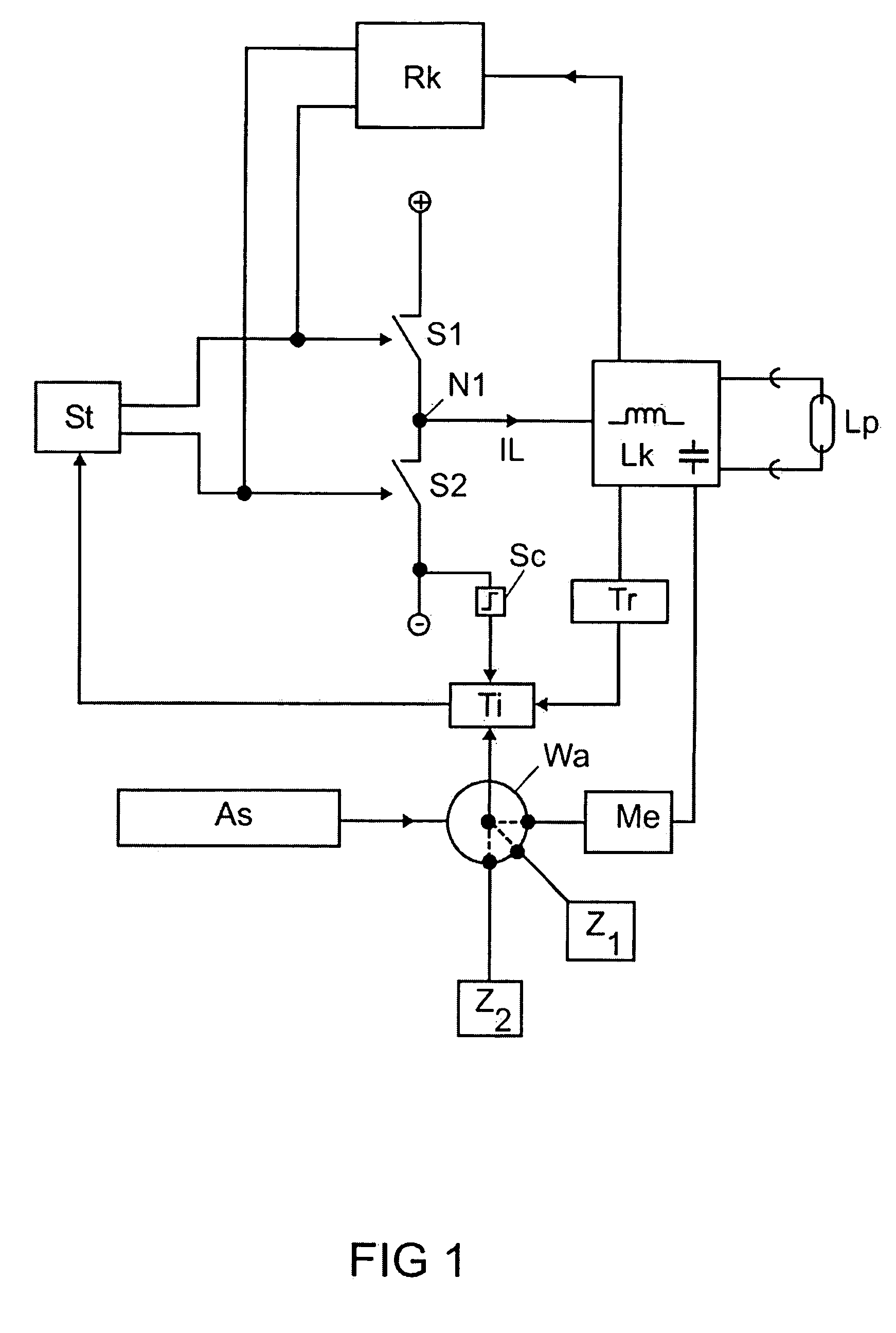
[0044]FIG. 1 shows a block diagram of a circuit arrangement according to the invention. An upper and a lower electronic switch S1, S2 are connected in series and form a half-bridge arrangement. At their junction point, S1 and S2 form a central point N1, to which a load circuit Lk is connected, in which a load current IL flows. Freewheeling diodes in parallel with S1 and S2 have not been illustrated, for the sake of clarity. The load circuit Lk contains a reactance network with one resonant frequency, to which a lamp Lp can be connected. The reactance network is schematically represented by an inductor and a capacitor. The reactance network is necessary in order to match the source impedance of the half-bridge arrangement to the load impedance which is formed by the lamp Lp. Gas discharge lamps require a power supply which has the character of a current source, while the half-bridge arrangement is fed from a voltage source, as is indicated by the circled plus and minus signs.

[0045]A ...


PUM


Abstract

Circuit arrangement having a free-running half-bridge inverter for operation of gas discharge lamps. A stop device is used to enable the drive to the half-bridge switches only during an on time. The oscillation frequency of the half-bridge inverter can be adjusted by the duration of the on time. This allows control of the lamp operating variables.

Description

FIELD OF THE INVENTION[0001]The invention relates to a circuit arrangement and to a method for operation of lamps. These are, in particular, self-oscillating half-bridge inverters whose oscillation frequency can be controlled or adjusted by means of the invention.[0002]The invention relates mainly to the operation of low-pressure gas discharge lamps, since equipment for lamps such as these is subject to major cost pressure. Except for aspects which relate to preheating, the invention can also be applied to equipment for high-pressure gas discharge lamps. The invention is also applicable for other light sources like LEDs.BACKGROUND OF THE INVENTION[0003]The document Fengfeng Tao, et al., “Self-Oscillating Electronic Ballast with Dimming Control”, Power Electronics Specialists Conference, 2001, IEEE, USA, describes a self-oscillating half-bridge inverter. FIG. 2 in this document shows a known half-bridge inverter with a feedback transformer. The electronic switches in this document ar...

Claims


Application Information

Patent Timeline
Patent Type & Authority Patents(United States)
IPC IPC(8): G05F1/00H05B44/00
CPCH05B41/3924H05B41/3925H05B41/382H05B41/2825Y02B20/185Y02B20/00H05B41/26H05B41/36
Inventor RUDOLPH, BERND
Owner PATENT TREUHAND GESELLSCHAFT FUR ELECTRIC GLUEHLAMPEN MBH
Why Eureka
Try Eureka