Digital circuit for frequency and timing characterization

a digital circuit and frequency characterization technology, applied in the direction of testing circuits, instruments, individual semiconductor device testing, etc., can solve the problems of increasing the testing time of the circuit, limiting the frequency being fed into the circuit, and inherently differing from the behavior of the actual silicon, so as to increase the accuracy of characterization for higher frequencies

Active Publication Date: 2007-07-10
STMICROELECTRONICS PVT LTD
View PDF4 Cites 3 Cited by
  • Summary
  • Abstract
  • Description
  • Claims
  • Application Information

AI Technical Summary

Benefits of technology

[0008]It is an object of the present invention to obviate the above-mentioned and other drawbacks and to provide an on-chip solution for frequency and timing characterization of integrated circuits so as to increase the accuracy of characterization for higher frequencies.
[0009]Another object of the present invention is to provide a characterizer that can characterize multiple integrated circuits and optimally determine a common operating frequency so as to provide synchronized operation of different circuits.

Problems solved by technology

The existing methods for testing digital circuits offer either frequency testing or duty cycle testing, but do not test for combinations of these parameters.
The frequency limitation of the IO pads limits the frequency being fed into the circuit.
The manual operations involved in the testing process further increase the testing time of the circuit.
Owing to these limitations, designers have to rely on simulation results, which inherently differ from the behavior on the actual silicon.
However, these approaches do not provide any mechanism to determine maximum operational clock frequency.
However, they do not compute the maximum operating frequency and also do not provide any mechanism to characterize both frequency and duty cycle.

Method used


Image

  • Digital circuit for frequency and timing characterization
  • Digital circuit for frequency and timing characterization
  • Digital circuit for frequency and timing characterization

Examples


Embodiment Construction

[0016]Preferred embodiments of the present invention will be described in detail hereinbelow with reference to the attached drawings.

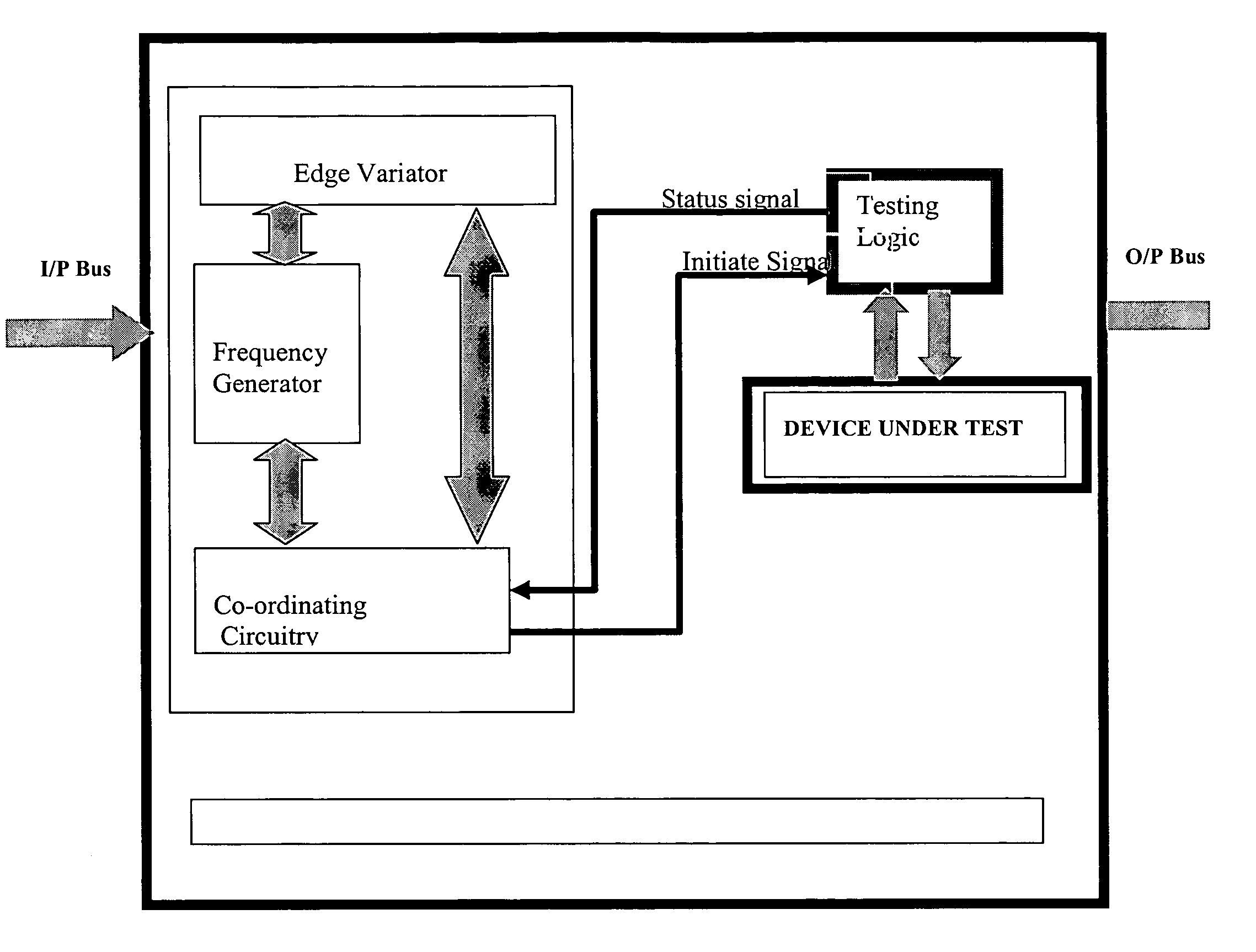
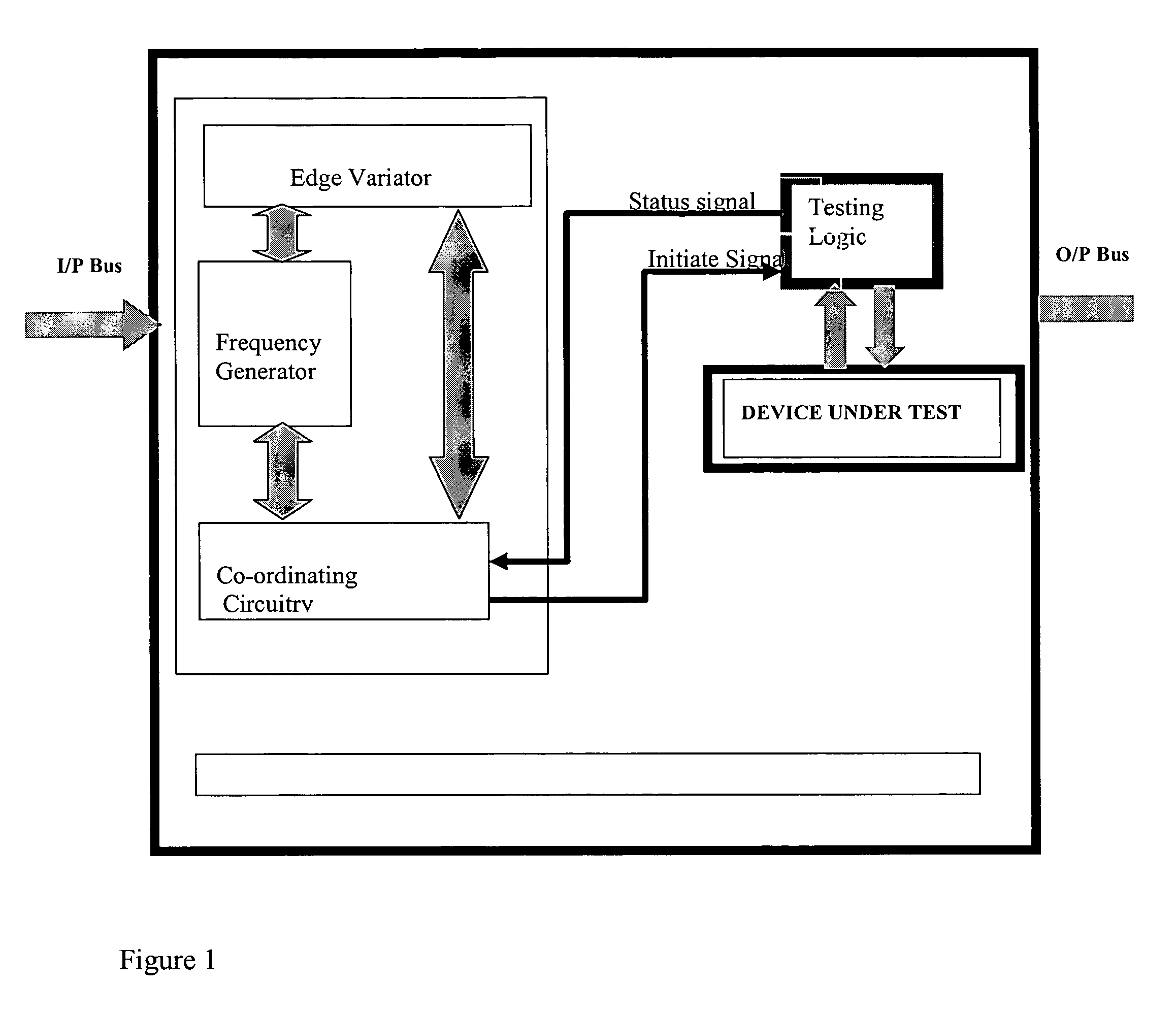
[0017]One preferred embodiment of the present invention provides an improved digital circuit operating frequency characterizer for providing a combination of frequency and duty cycle characterization. The characterizer includes a programmable frequency generator, a programmable edge variator, a test engine, and a control circuit. The programmable frequency generator provides one or more output signals, and the programmable edge variator is coupled to at least one output of the programmable frequency generator for adjusting duty cycle. The test engine uses the outputs from the programmable edge variator and / or programmable frequency generator to apply a defined test signal sequence to the circuit under test and produces a status output after evaluating the received outputs. The control circuit is connected to the control inputs of the programmable frequ...


PUM


Abstract

A digital circuit operating frequency characterizer provides a combination of frequency and duty cycle characterization. The digital circuit operating frequency characterizer includes a programmable frequency generator, a programmable edge variator, a test engine, and a control circuit. The programmable frequency generator provides one or more output signals, and the programmable edge variator is coupled to one or more outputs of the programmable frequency generator for adjusting duty cycle. The test engine uses the outputs from the programmable edge variator and / or programmable frequency generator to apply a defined test signal sequence to a circuit under test and produce a status output after evaluating the outputs received from the circuit under test. The control circuit is connected to the control inputs of the programmable frequency generator, programmable edge variator, and the status output of the test engine. The control circuit synchronizes their operations and performs the combination of frequency and duty cycle characterization.

Description

CROSS-REFERENCE TO RELATED APPLICATIONS[0001]This application is based upon and claims priority from prior Indian Patent Application No. 1619 / Del / 2003, filed Dec. 26, 2003, the entire disclosure of which is herein incorporated by reference.FIELD OF THE INVENTION[0002]The present invention relates to an improved digital circuit for frequency and timing characterization, and more particularly to on chip timing and frequency characterization.BACKGROUND OF THE INVENTION[0003]In order to exactly determine the performance of digital circuits, it is required to test them for different frequencies and duty cycles. The existing methods for testing digital circuits offer either frequency testing or duty cycle testing, but do not test for combinations of these parameters. Also, the conventional testers are generally external to the chip. The tester applies different frequencies to the circuit through the IO pads. The frequency limitation of the IO pads limits the frequency being fed into the c...

Claims


Application Information

Patent Timeline
Patent Type & Authority Patents(United States)
IPC IPC(8): G01R31/28G01R31/317G01R31/319H03B19/00
CPCG01R31/31727G01R31/31922
Inventor SARASWAT, RUCHIRSINGH, BALWANTMUSHIR, HINA
Owner STMICROELECTRONICS PVT LTD
Why Eureka
Try Eureka