Imaging apparatus suppressing an occurrence of color moire

a color moire and image sensor technology, applied in the field of high-definition electronic still imaging apparatus, can solve the problems of difficult to display based on readout of all the pixels of the image sensor having several million pixels, difficult to take an image sensor having several-million pixels, and theoretical upper limit, so as to reduce the flicker of images

Inactive Publication Date: 2007-07-10
OLYMPUS CORP
View PDF13 Cites 35 Cited by
  • Summary
  • Abstract
  • Description
  • Claims
  • Application Information

AI Technical Summary

Benefits of technology

[0010]It is a first object of the present invention to provide an imaging apparatus in which an occurrence of spurious signals is prevented even when movie is read out at a standard frame rate (NTSC rate) from a high-resolution image sensor. Further it is a second object of the invention to provide an imaging apparatus in which an occurrence of color moire is suppressed at a single imager of color filter array (CFA) system which is used for the purpose of cost-cutting / compacting.
[0014]The technical contents corresponding to the second aspect are shown in FIGS. 7, 17, 21, and 25 to 28. In thus constructed imaging apparatus, the sampling number can be reduced by the discrete arrangement of the plurality of readout pixel location regions from each other and the lack of image information due to the reduced sampling number can be interpolated by interframe that the readout pixel locations are varied frame by frame. It is also possible to achieve a higher frame rate by reducing the sampling number.
[0030]The technical contents corresponding to the tenth aspect are shown in FIGS. 14A, 14B. In thus constructed imaging apparatus, color moire can be reduced without reducing the resolution of image as a whole by computing chromatic component from the regions at which the averaging is performed and by computing luminance information from the regions at which the averaging is not performed. Further, it becomes possible to reduce moire at specific frequency by varying the sampling frequency and phase region by region.
[0037]The technical contents corresponding to the thirteenth aspect are shown in FIGS. 22A to 28. In thus constructed imaging apparatus, the difference detecting means of luminance information between frames is provided so that inter-frame interpolation can be stopped and switching be made to an intra-frame interpolation in those images having relatively small correlation between frames. It is thus possible to reduce flicker of image in the case where Y / C composition in consecutive frames is performed.

Problems solved by technology

Considering the operation clock of pixels, it is generally difficult for an image sensor having several-million pixels to take 30 frames per second as at NTSC rate (For Example 5 M pixel picture is limited to take 8 frames per second for a pixel clock of 40 MHz.
However this is the theoretical upper limit.
For this reason, a displaying based on readout of all the pixels of the image sensor having several million pixels is very difficult or costly, and only the pixels of a number required for a displaying at EVF are read out (thinned-out readout or averaging readout) so as to effect a real-time display.
Generally, lack of resolution is known to cause moire due to folding of a texture having a higher frequency than the sampling frequency.
However, it is difficult to read all of the pixels to obtain a high-quality movie because of limitations on the frame rate of movies and on the operation clock of an image sensor as described above.
In using this method, however, there is a problem that an occurrence of capacity overflow of transfer area causes a degradation of signals.

Method used


Image

  • Imaging apparatus suppressing an occurrence of color moire
  • Imaging apparatus suppressing an occurrence of color moire
  • Imaging apparatus suppressing an occurrence of color moire

Examples


first embodiment

[0094]As a first specific embodiment of the invention, a description will now be given with respect to an imaging apparatus in which rectangular blocks having different phase are read out with shifting the location of sampling frame by frame. The respective block image data of consecutive frames read out at the shifted locations are then compared with each other to select a block image data with least false color so as to suppress the color moire. FIG. 7 is a block diagram showing the imaging apparatus based on such technique.

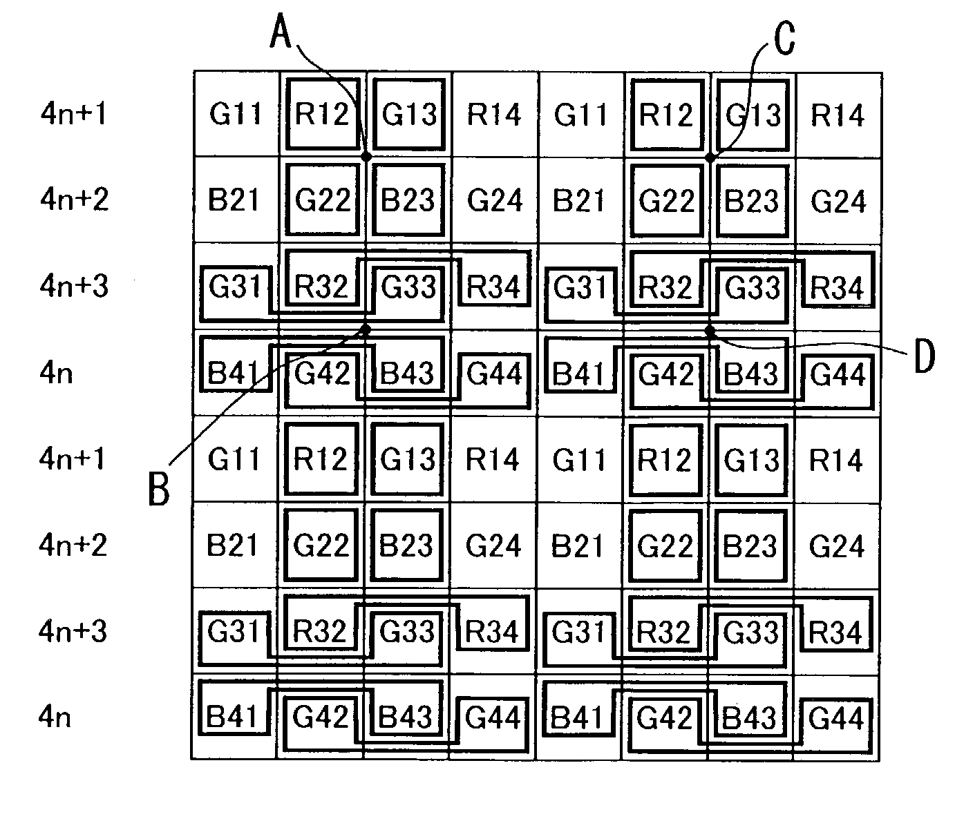
[0095]In this embodiment, as in FIG. 8A, an example is shown of change into an image having 1 / 16 size by dividing the image data into basic blocks each having 4×4 pixels. Each basic block is further divided into four sampling read unit blocks A, B, C, D each being a set of RGB of 2×2 pixels. The readout is then performed by shifting the sampling location of the read unit blocks frame by frame (phase shifted readout) such that unit block A is read out at I-th fr...

second embodiment

[0111]In an image sensor having CFA thereon, an identical processing as linear interpolation can be performed by an averaging of pixels. Even at a pixel of the location at which it is in actuality impossible to obtain pixel value of a subject color, a pixel value of the subject color at that location is artificially produced by means of such processing as interpolation. Generally, in a regularly arranged CFA such as Bayer matrix, since sampling lattice is regular for each color in the intermittent processing, color moire due to high-frequency pattern of object is caused to occur.

[0112]To suppress an occurrence of color moire, a method of applying phase shift is a consideration in addition to the method for limiting band by a low-pass filter as in the above described interpolation processing. A system for artificially performing phase shift of readout by using an averaging read will thus be shown as a second embodiment. A description will be given on assumption that signals of CFA of...

third embodiment

[0124]A third embodiment will now be described. In this embodiment, in order to reduce moire of Y signal (luminance moire) in performing Y / C separation processing in the second embodiment, luminescence (Y) signals, after once read out in the direction of line, are passed through a low pass filtering operation, and resized with a subsampling. In particular, instead of the sampling rule (pattern) shown in FIGS. 18A, 18B, Y / C separation / composite processing is performed as shown in FIGS. 19A, 19B by using a combination of two readout lines of only G channel and two lines of averaging read, i.e. Y signal obtained from sampling of G channel of two lines and Cb, Cr signals obtained from averaging read of two lines.

[0125]At this time, the number of operation pulse of readout line of G channel is the same as the example shown in FIGS. 18A, 18B. For example, sampling of G is performed twice in one line of 4×4 block (second and third columns of block A of FIGS. 19A, 19B). Further, its timing ...


PUM


Abstract

An imaging apparatus for outputting image signals by photoelectrically converting an image formed at an optical system by an image sensor array having a color filter array having several spectral transmittance disposed in front thereof, including: mode setting means capable of setting at least one mode among an all-pixel read mode for effecting readout of all the pixels of at least one horizontal line, an intermittent read mode for effecting readout in a thinned-out manner of pixels to be read out from at least one horizontal line, and an averaging read mode for effecting readout by averaging a plurality of pixels as the mode for reading out image signals from the image sensor array; and readout rule control means for controlling and determining pixel locations for reading out the image signals: when the intermittent read mode and / or the averaging read mode have been set by the mode setting means, the readout pixel locations to be determined by the readout rule control means are caused to vary frame by frame in the image signals to be read out.

Description

[0001]This application claims benefit of Japanese Patent Application No. 2002-147136 filed in Japan on May 22, 2002, the contents of which are incorporated by this reference.BACKGROUND OF THE INVENTION[0002]The present invention relates to imaging apparatus, and more particularly relates to high-definition electronic still imaging apparatus having a liquid crystal view finder and also to imaging apparatus capable of both movie taking and high-definition still image taking.[0003]Because of the rapid spreading of personal computers in recent years, there is an increasing demand for digital cameras (electronic still camera) as an image input equipment. Also, high-quality image recording apparatus such as digital camcorder are widely used as a recording equipment of movies. Among the several factors by which an image quality of the above described electronic still camera is determined, the number of pixels of image sensor is a major factor for determining the resolution of taken image. ...

Claims


Application Information

Patent Timeline
Patent Type & Authority Patents(United States)
IPC IPC(8): H04N5/222H01L27/146H04N5/232H04N5/335H04N5/341H04N5/349H04N5/351H04N5/357H04N5/374H04N9/07
CPCH04N3/1562H04N9/045H04N25/445H04N25/46H04N25/767
Inventor WATANABE, NOBUYUKI
Owner OLYMPUS CORP
Why Eureka
Try Eureka