Low strain optical fiber cable

a technology of optical fiber and low strain, applied in the direction of optics, fibre mechanical structures, instruments, etc., can solve the problems of inadequate cable design, degraded fiber performance, and fiber breakage, and achieve the effect of not suffering significant strain or degradation in performan

Inactive Publication Date: 2007-07-10
VERIZON PATENT & LICENSING INC
View PDF11 Cites 56 Cited by
  • Summary
  • Abstract
  • Description
  • Claims
  • Application Information

AI Technical Summary

Benefits of technology

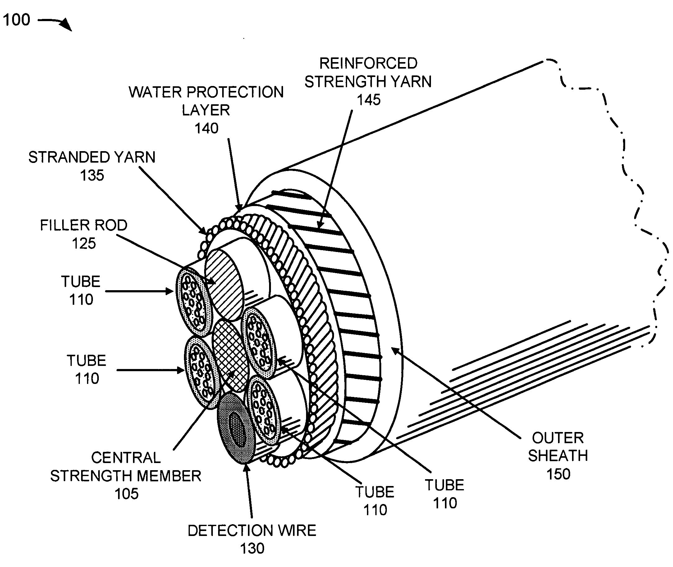
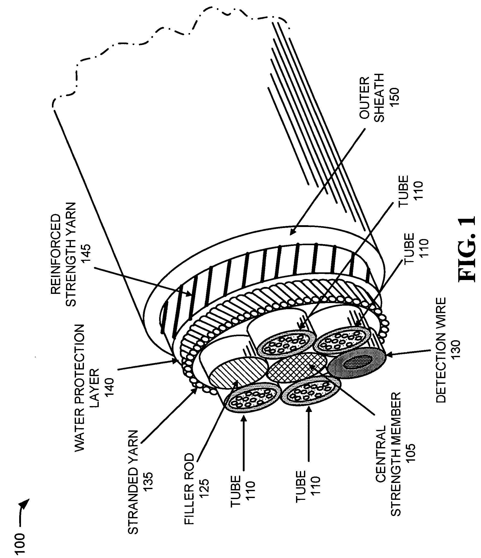
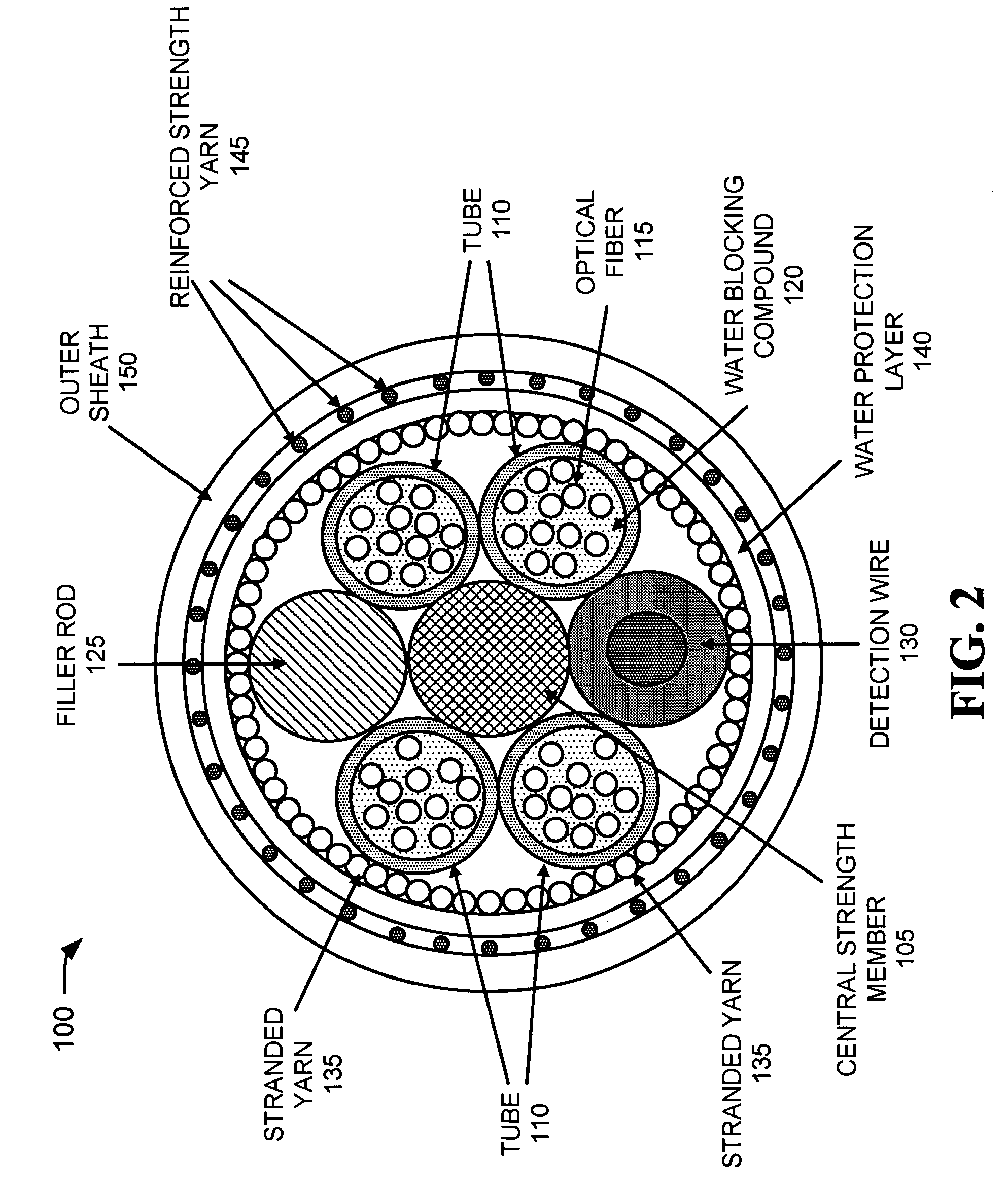
[0006]According to another aspect consistent with the principles of the invention, an optical fiber assembly is provided. The optical fiber assembly includes a strength member and multiple tubes, where optical fibers are disposed within the multiple tubes. The optical fiber assembly further includes a reinforced structure surrounding the multiple tubes and the strength member, where the reinforced structure does not experience any significant strain until a tension upon the fiber assembly on the order of 600 pounds is reached. The optical fiber assembly may alternatively be characterized in that optical fibers within the fiber assembly do not suffer significant strain or degradation in performance even when a tension of at least 600 pounds is applied to the overall fiber cable assembly.

Problems solved by technology

Installations exceeding one or two thousand feet present challenges in fiber cable breakage and degraded fiber performance.
Inadequate cable designs allow excessive installation forces to be imparted to fibers within the cable.
“Backbone” or “long haul” optical fiber installations spanning inter-city distances of tens or hundreds of miles are considerably more difficult to achieve using convenient cable blowing techniques.
When conventional fiber cables designed for building riser applications are applied to long haul installations, they are susceptible to breakage or excessive strain resulting in risky installations and poor fiber performance.

Method used


Image

  • Low strain optical fiber cable
  • Low strain optical fiber cable
  • Low strain optical fiber cable

Examples


Embodiment Construction

[0014]The following detailed description of the invention refers to the accompanying drawings. The same reference numbers in different drawings may identify the same or similar elements. Also, the following detailed description does not limit the invention. Instead, the scope of the invention is defined by the appended claims and their equivalents.

[0015]An optical fiber assembly consistent with the principles of the invention improves the protection provided to optical fiber installations. Optical fiber protection is improved through the use of a reinforced cable structure that has a yield strength and / or tensile strength rating that is higher than existing blown optical fiber cables which are small enough for blown installation. Thus, fiber performance should not be degraded when employing existing cable blowing or pulling techniques for installing the optical fiber cable. An optical fiber assembly consistent with the principles of the invention is preferably a ‘microcable’ designe...


PUM


Abstract

An optical fiber assembly includes a central strength member, multiple tubes, stranded yarn, a water protection layer, reinforced strength yarns and an outer sheath. At least one of the multiple tubes has one or more optical fibers disposed within. The stranded yarn is formed around the multiple tubes and the central strength member. The water protection layer is formed around the stranded yarn. The reinforced strength yarns are formed around the water protection layer and the outer sheath is formed around the reinforced strength yarns. The optical fiber assembly has an overall diameter of less than about 11.5 mm and exhibits low strain when subjected to a tension of at least 600 pounds.

Description

CROSS REFERENCE TO RELATED APPLICATION[0001]The instant application claims priority from provisional application Nos. 60 / 547,785 and 60 / 547,786, both filed Feb. 27, 2004, the disclosures of which are incorporated by reference herein in their entirety.FIELD OF THE INVENTION[0002]Implementations consistent with the principles of the invention relate generally to optical fiber cables and, more particularly, to low strain optical fiber cables.BACKGROUND OF THE INVENTION[0003]With the explosion in communication via the Internet in recent years, there has been a corresponding increase in demand for high bandwidth communications, such as that provided by optical fibers. Optical fiber cables have been deployed over short distances ranging from a few hundred feet, such as within a building or between nearby buildings, to a few thousand feet in some metropolitan and fiber-to-the-curb installations. Various techniques for pulling or blowing of communication fibers have been employed for both i...

Claims


Application Information

Patent Timeline
Patent Type & Authority Patents(United States)
IPC IPC(8): G02B6/44
CPCG02B6/441G02B6/4432G02B6/4434G02B6/447G02B6/4494G02B6/562G02B6/44384
Inventor FEE, JOHN A.
Owner VERIZON PATENT & LICENSING INC
Why Eureka
Try Eureka