Wind driven sailing craft

a technology for sailing boats and wind turbines, which is applied in the direction of marine propulsion, special-purpose vessels, vessel construction, etc., can solve the problems of preventing the aft of the craft from sinking lower into the water, creating drag that is detrimental to the performance of the craft, and reducing the displacement. , the effect of reducing drag

Inactive Publication Date: 2007-07-17
COMPASS MARINE DEV
View PDF6 Cites 10 Cited by
  • Summary
  • Abstract
  • Description
  • Claims
  • Application Information

AI Technical Summary

Benefits of technology

[0017]The sailing craft can be provided with a drop, or a swing, keel, which is lowered into position to provide ballast when the craft is sailing, and is raised to reduce drag when the craft is propelled forwards by power propulsion means. Further, the craft can also be provided with internal water ballast tanks which can be filled with water to provide ballast when sailing, and emptied to reduce the displacement when the craft is propelled forwards by power propulsion means.
[0018]When the craft is being powered by its sails the hydrofoil is set level to the water flow under the after end of the hull so zero lift and minimum drag are provided and the hull operates as a normal sailing hull. It has been found that the hydrofoil provides stability to the hull when the craft is being sailed and acts as a damper in rough conditions, which are additional benefits.
[0019]In one construction the hydrofoil is disposed approximately level with the base line of the hull. However, in another construction the hydrofoil is disposed approximately level with the base line of the drop keel. It has been found that with either of these arrangements when the craft is grounded or removed from the water it can be supported in an upright po...

Problems solved by technology

As a result the “foils” create drag which is detrimental to the performance of the craft when sailed and in particular when heeled over.
As a result the lifting force prov...

Method used


Image

  • Wind driven sailing craft
  • Wind driven sailing craft
  • Wind driven sailing craft

Examples


Embodiment Construction

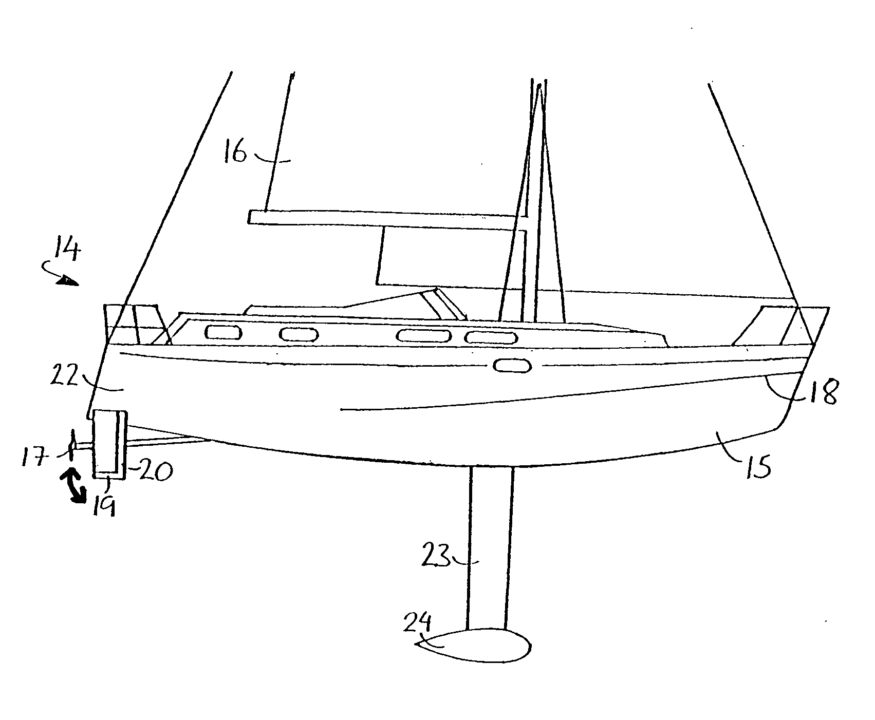
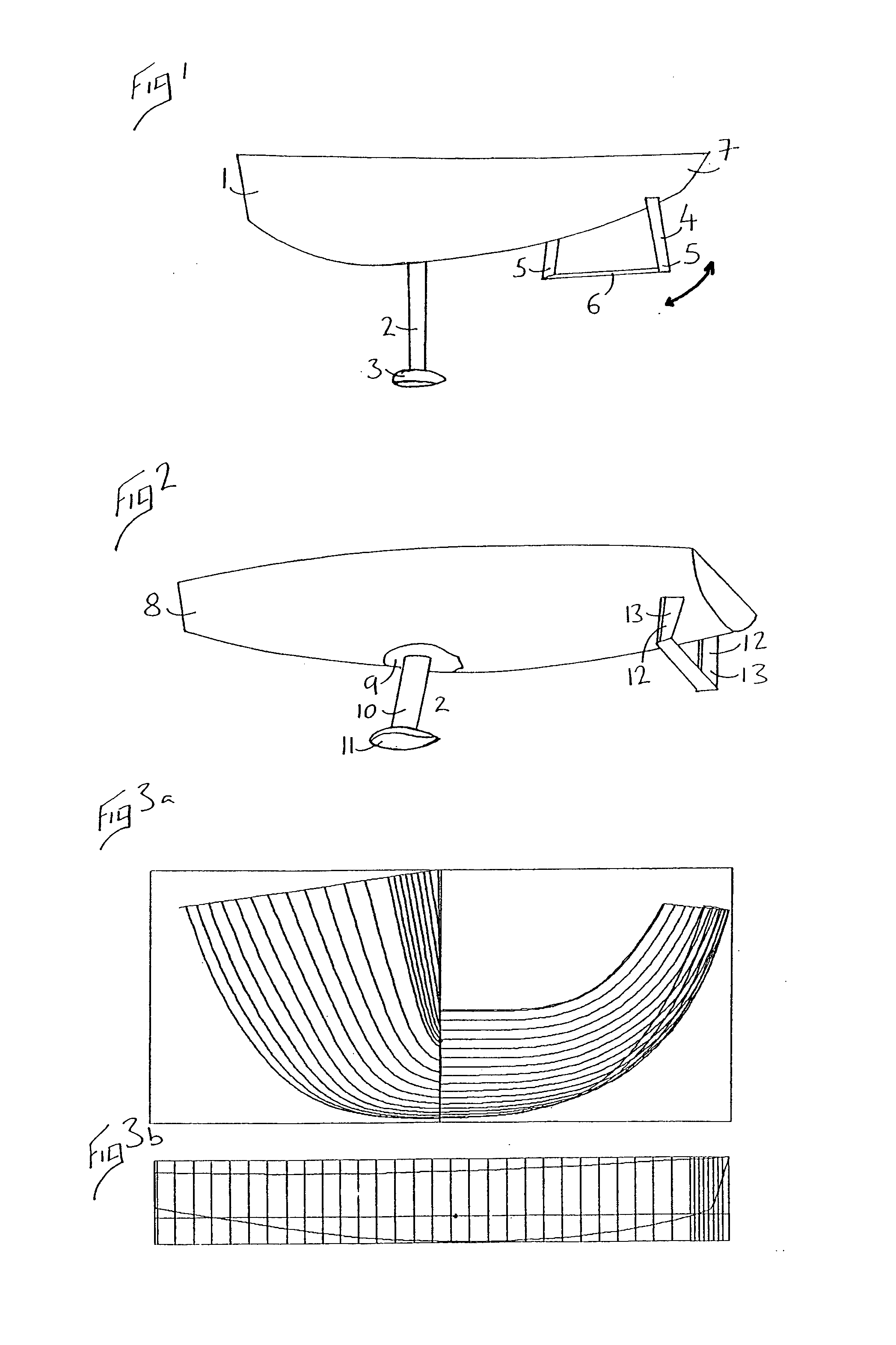
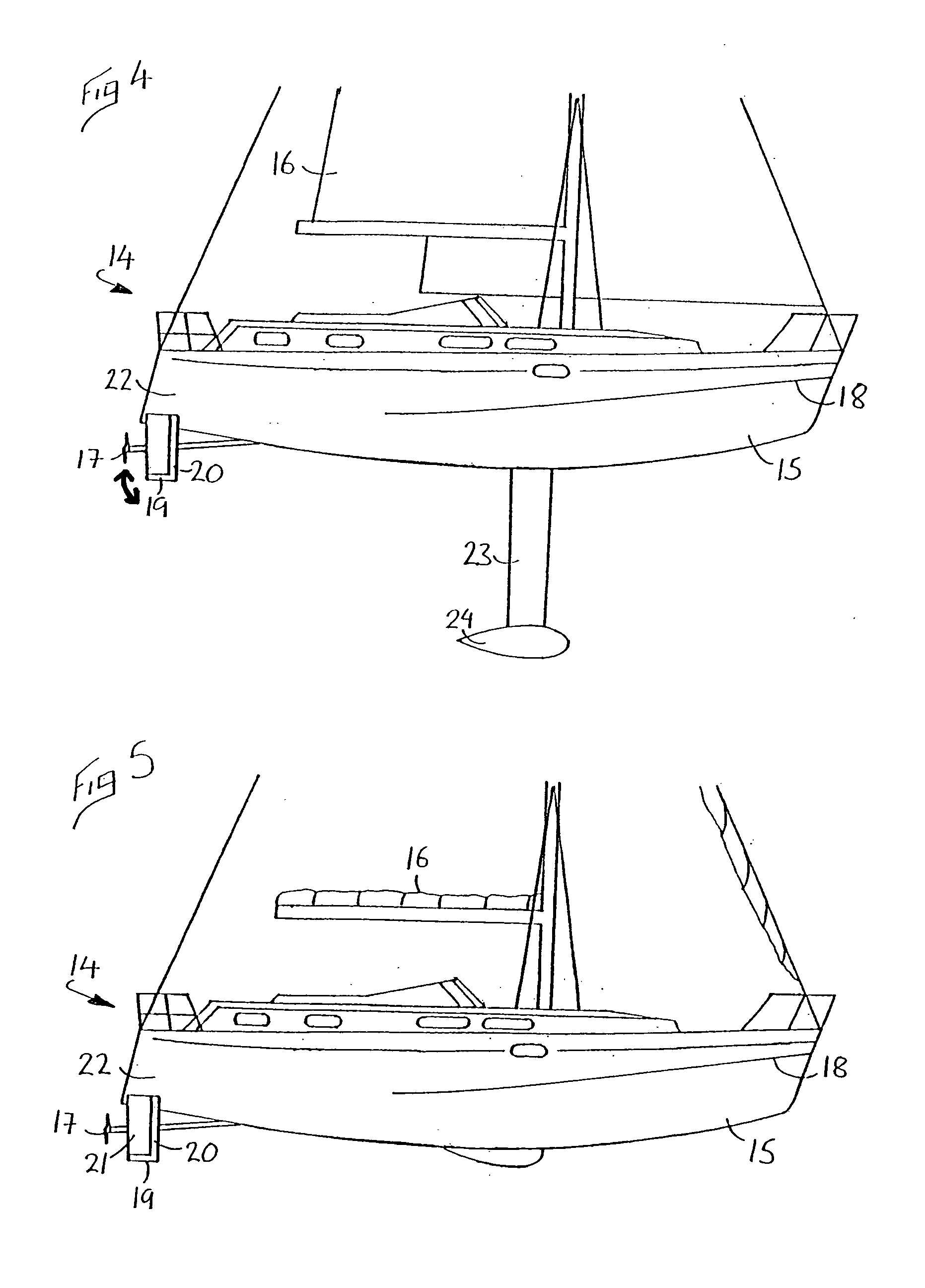
[0036]FIGS. 1 shows a displacement boat hull 1 which is shaped for sailing and is approximately 13 meters in length. FIGS. 3a and 3b show the cross-sectional contours of the hull 1. The hull 1 has a broad beam to provide sufficient righting moment to support the sails and provide an adequate lever arm for internal water ballast. In other respects the hull 1 is a shaped for high-speed sailing (approximately 10 knots). As shown in FIG. 1 the hull 1 is provided with a drop keel 2 with a ballast bulb 3, and a hydrofoil element 4. The hydrofoil element 4 comprises two struts 5 and an interconnecting horizontal wing 6. The wing 6 is substantially rectangular in shape with the shorter sides thereof disposed substantially parallel to the direction of the hull 1. The hydrofoil element is mounted adjacent to the aft 7 of the hull 1.

[0037]In FIG. 2 displacement boat hull 8 is identical to the hull 1 shown in FIG. 1, except for recess 9 provided on the lower surface. Recess 9 is dimensioned to ...


PUM


Abstract

A wind driven sailing craft is disclosed with a hydrofoil element which provides variable lift to the stern of the craft to maintain a level trim when the craft is operated under power propulsion. The hydrofoil element includes a hydrofoil wing which rotates on a transverse axis to provide the desired lift.

Description

BACKGROUND OF THE INVENTION[0001]This application is the U.S. National Phase of PCT Application Number PCT / GB03 / 00373, filed on 29 Jan. 2003, which claims priority to Great Britain Application Number 0202142.6, filed 30 Jan. 2002.[0002]This invention relates to a watercraft which may be used for sailing using wind power, but which can maintain a level trim when mechanically propelled at high speeds.[0003]1. Field of Invention[0004]Sailing craft can be provided with a displacement mono-hull with a transverse cross-section which tapers downwardly on each side to its keel line, and which increases in cross-section from the bow to a fullest transverse section, and decreases in cross section from the fullest transverse section to the after end. Such a mono-hull shape is suitable for sailing because of its streamlined longitudinal shape when upright and when heeled over.[0005]However, displacement mono-hulled sailing craft as described above are not suitable to be mechanically propelled a...

Claims


Application Information

Patent Timeline
IPC IPC(8): B63B1/24B63B39/06B63H9/00B63B1/26B63B41/00
CPCB63B1/24B63B39/06B63B2035/009B63B41/00
Inventor CHESNEY, JOHNCLARKE, REGINALDCLAUGHTON, ANDREW
Owner COMPASS MARINE DEV
Why Eureka
Try Eureka