Implantable penile prosthesis pump

a penile prosthesis and pump technology, applied in the field of erectile dysfunction and other urological disorders, can solve the problems of reservoir compression and corresponding spontaneous inflation of cylinders, and achieve the effect of reducing the chance of reservoir compression and corresponding spontaneous inflation of cylinders, and implantation procedures that are typically less complicated

Active Publication Date: 2007-07-17
BOSTON SCI SCIMED INC
View PDF42 Cites 40 Cited by
  • Summary
  • Abstract
  • Description
  • Claims
  • Application Information

AI Technical Summary

Benefits of technology

[0007]The present invention provides certain advantages over other known two-piece and three-piece implantable and inflatable penile prostheses systems. With regard to the two-piece system of the present invention, the use of a pressurized reservoir as an energy-storing device or component aids in providing significant fluid transfer to the cylinders with a single type of motion. That is, the motion that is used to activate the pump is the same motion that is performed to inflate the cylinders. This system thus requires relatively less complicated manipulation to achieve inflation of the cylinders than other commercially available systems. Additionally, because there is not a separate reservoir to implant in the abdomen, the implantation procedure would typically be less complicated than for a system with a separate reservoir. In addition, because there is no reservoir in the abdomen, the chance of reservoir compression and corresponding spontaneous inflation of cylinders is decreased.

Problems solved by technology

In addition, because there is no reservoir in the abdomen, the chance of reservoir compression and corresponding spontaneous inflation of cylinders is decreased.

Method used


Image

  • Implantable penile prosthesis pump
  • Implantable penile prosthesis pump
  • Implantable penile prosthesis pump

Examples


Embodiment Construction

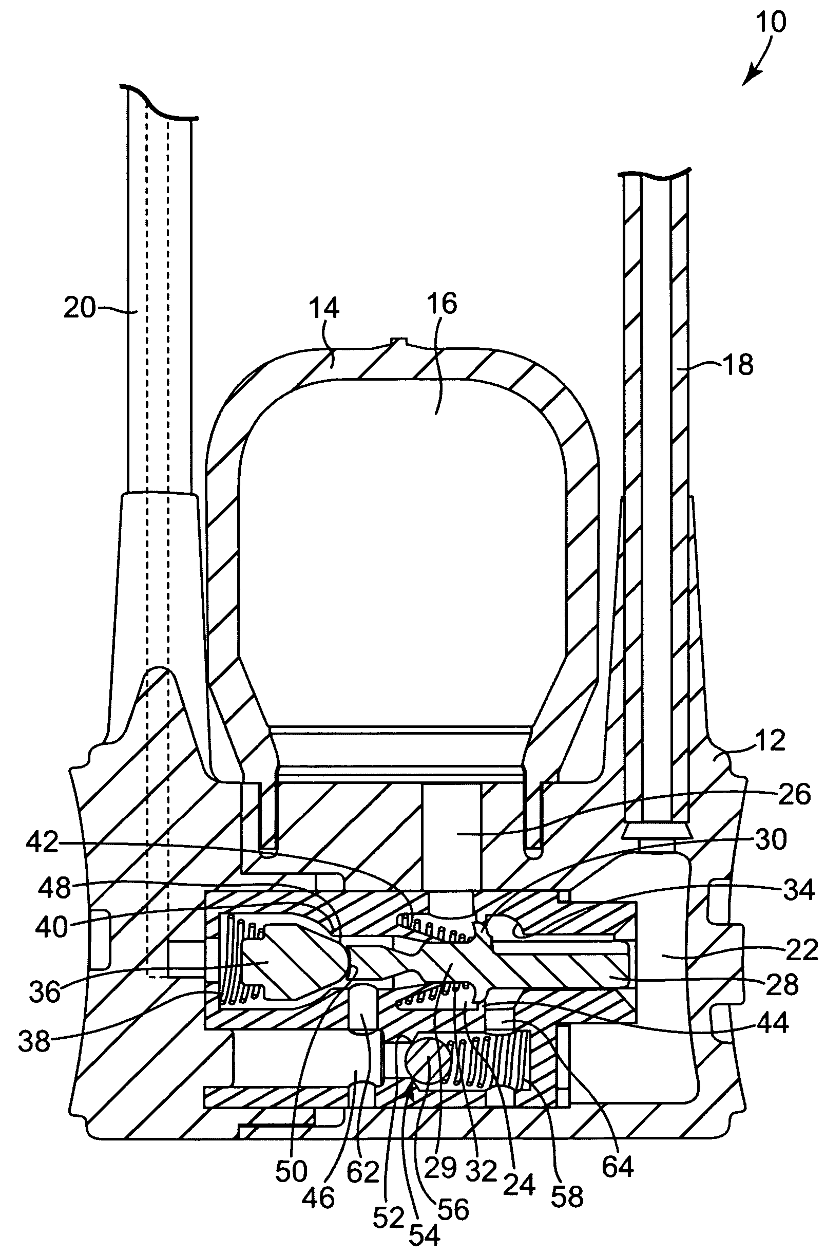
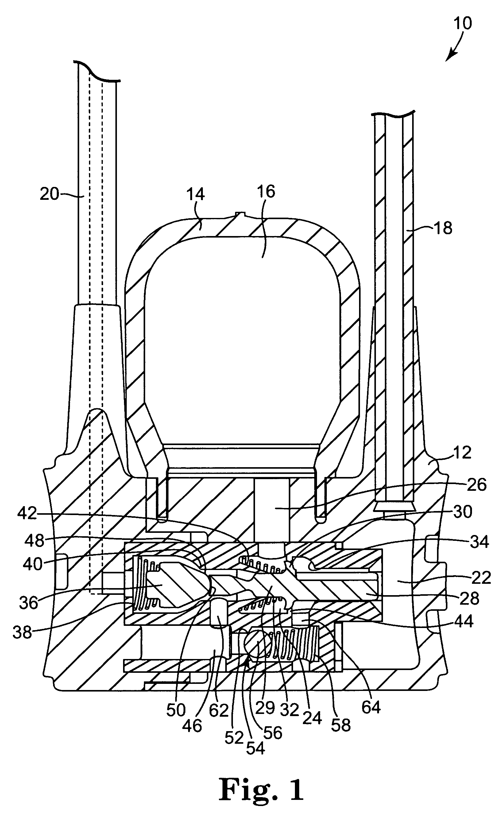
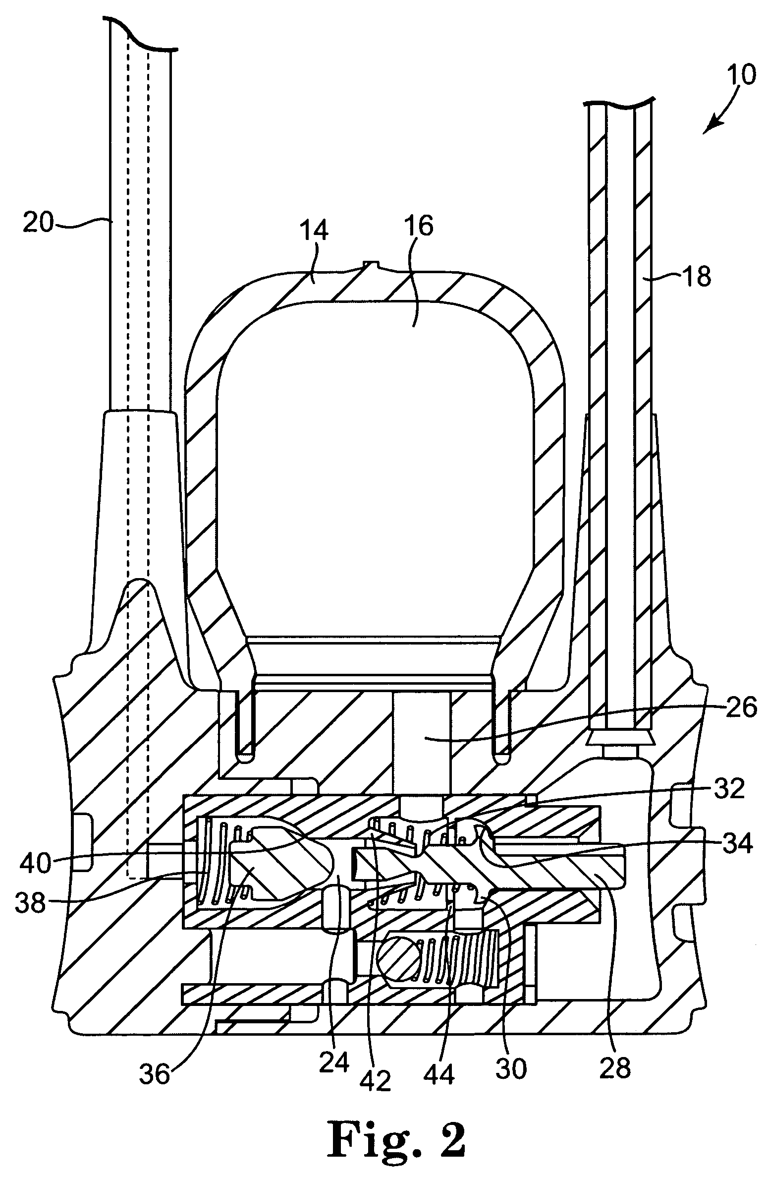
[0023]Referring now to the Figures, wherein the components are labeled with like numerals throughout the several Figures and initially to FIG. 1, one preferred configuration of a pump assembly 10 for use in an implantable penile prosthesis system is illustrated. In general, when the penile prosthesis system is implanted into a person, the pump assembly 10 is positioned within the user's scrotum, two inflatable cylinders are positioned within the user's corpus cavernosae and a reservoir is implanted in the user's abdomen. One or more tubes provide fluid communication between the assembly 10 and the cylinders and between the assembly 10 and the reservoir. In this embodiment, the assembly 10 includes a housing or pump body 12 connected to a pump bulb 14 having an internal pump chamber 16. The pump assembly 10 is connected for fluid communication with at least one inflatable cylinder (not shown) by at least one tube 20, which may be a flexible silicone tube, for example. While only one ...


PUM


Abstract

A penile prosthesis is provided, which includes at least one cylinder, a reservoir, and a pump including a pump housing, at least one reservoir channel fluidly coupling the pump housing to the reservoir, at least one cylinder tube fluidly connecting the pump housing to the cylinders, and a fluid passageway fluidly coupled to the cylinder tube and a transfer chamber. The pump further includes a first poppet and a second poppet, each of which is biased toward its respective valve seat within the fluid passageway. A bypass chamber is fluidly connected to the fluid passageway by a bypass input channel and a bypass output channel. The bypass chamber comprises a bypass check valve biased toward a closed position. The pump also includes a pump bulb fluidly connected to the fluid passageway between the bypass input channel and bypass output channel along the length of the fluid passageway.

Description

REFERENCE TO RELATED APPLICATIONS[0001]This application claims the benefit of U.S. Provisional applications having Ser. No. 60 / 453,684, filed Mar. 10, 2003, entitled “IMPROVED IMPLANTABLE PUMP,” and Ser. No. 60 / 508,123, filed Oct. 2, 2003, entitled “IMPLANTABLE PENILE PROSTHESIS HAVING A PRESSURIZED RESERVOIR,” which applications are incorporated herein by reference in their entirety.TECHNICAL FIELD[0002]The present invention relates to systems for treating erectile dysfunction and other urological disorders. In particular, the invention relates to inflatable implantable penile prostheses.BACKGROUND OF THE INVENTION[0003]One common treatment for male erectile dysfunction includes the implantation of a penile implant device. One type of penile implant device includes a pair of cylindrical prostheses that are implanted into the corpus cavernosae of the penis. Typically, the cylindrical prostheses or cylinders are inflatable and are connected to a fluid-filled reservoir through a pump ...

Claims


Application Information

Patent Timeline
Patent Type & Authority Patents(United States)
IPC IPC(8): A61F5/00A61F2/26
CPCA61F2/26
Inventor MORNINGSTAR, RANDY L.
Owner BOSTON SCI SCIMED INC
Why Eureka
Try Eureka