

Vascular prosthesis and method for production thereof
a vascular prosthesis and vascular technology, applied in the direction of prosthesis, open-end spinning machines, blood vessels, etc., can solve the problems of weakening the ability of the graft to remain in the proper position inside the body vasculature, reducing the mechanical and tensile strength of the graft, and high blood permeability during and after implantation
- Summary
- Abstract
- Description
- Claims
- Application Information
AI Technical Summary
Benefits of technology
Problems solved by technology
Method used
Image

Examples
example 1
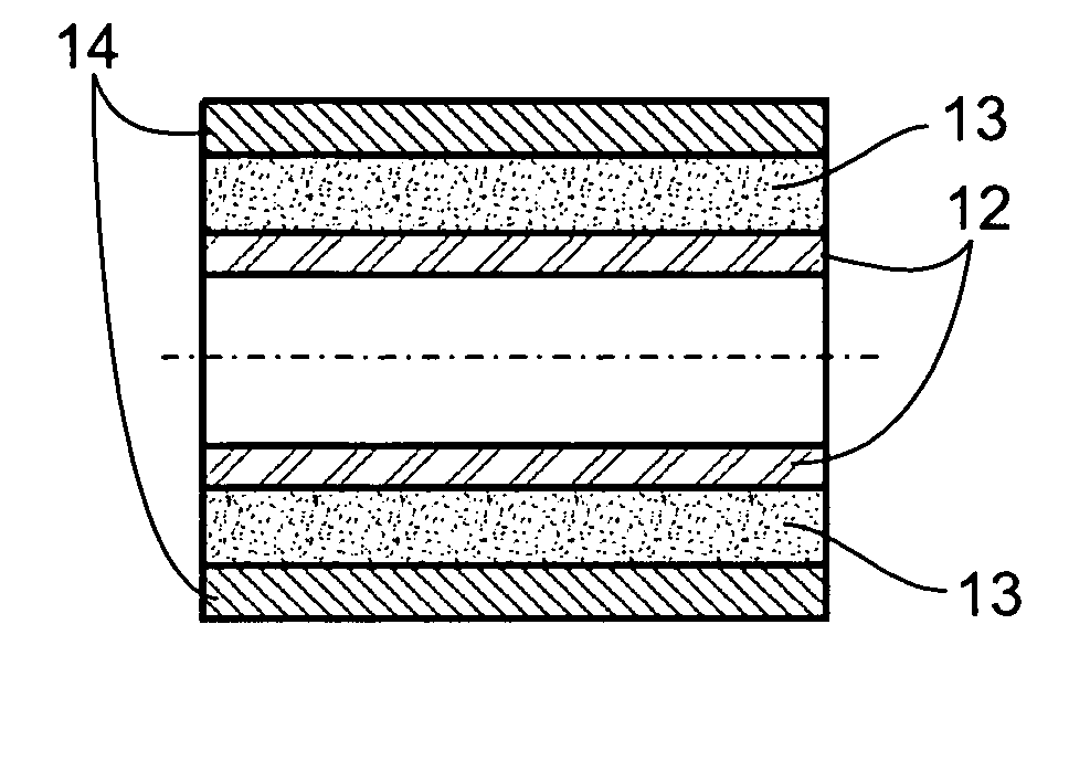
A Two Layer Graft
[0136]A vascular prosthesis 6 mm in diameter and 200 mm in length was manufactured. A rod with 6 mm in diameter and 300 mm in length was used as a mandrel, and its central 200 mm portion was coated at ambient temperature, 24° C. Pump productivity was 3 ml / h.
[0137]CarboSil 20 polyuurethane solution was used to form both the inner layer and the outer layer, the thickness of which was 80 μm and 720 μm respectively, hence the total wall thickness was 800 μm. In the inner layer, the viscosity of the solution was 450 cP and the conductivity was 0.45 μS, and in the outer layer, the viscosity was 680 cP and the conductivity 1.8 μS. The graft was removed from the mandrel, rinsed repeatedly in deionized water, dried and sterilized.
Results
[0138]The mechanical parameters of the graft according to ISO 7198:1998 (E), were: general porosity of 68%, kinking diameter of 30 mm and dynamic compliance of 9%.
example 2
The Effect of Solution Viscosity
[0139]A vascular prosthesis 6 mm in diameter and 200 mm in length was manufactured as described in Example 1, however for both inner layer and outer layer equal solution viscosity of 450 cP and equal conductivity of 0.45 μS was used. In addition, the pump productivity was increased to 5 ml / h.
Results
[0140]The above changes lead to a slightly higher value of general porosity but lower anti-kinking strength and compliance. The mechanical parameters of the graft according to the ISO were: general porosity of 70%, kinking diameter of 35 mm and dynamic compliance of 8%.
example 3
The Effect of a Predetermined Fiber Orientation
[0141]A vascular prosthesis 6 mm in diameter and 200 mm in length was manufactured, as in Example 2, with the outer layer being formed from fibers placed in transverse (polar) orientation, for enhancing the radial strength of the graft. In addition, the thickness of the outer layer was 520 μm, hence total wall thickness reduced to 600 μm.
Results
[0142]The above changes lead to-improvement of both antikinking resistance and dynamic compliance, without scarifying the general porosity. The mechanical parameters of the graft according to the ISO were: general porosity of 70%, kinking diameter of 32 mm and dynamic compliance of 10%.
PUM
| Property | Measurement | Unit |
|---|---|---|
| thickness | aaaaa | aaaaa |
| thickness | aaaaa | aaaaa |
| diameter | aaaaa | aaaaa |
Abstract
Description
Claims
Application Information