
Electronic apparatus that allows cooling fan to be driven with certainty even at the time of software malfunction/lock-up or at the time of controller failure

a technology of electronic equipment and cooling fan, which is applied in the direction of motor/generator/converter stopper, dynamo-electric converter control, instruments, etc., can solve the problems of failure to perform the appropriate control of the cooling fan, the function of protecting the cpu may not be performed, and the size of the device to be increased

Inactive Publication Date: 2007-07-17
KK TOSHIBA
View PDF16 Cites 15 Cited by
  • Summary
  • Abstract
  • Description
  • Claims
  • Application Information

AI Technical Summary

Benefits of technology

Ensures reliable operation of the cooling fan to protect the CPU by allowing independent drive control without relying on the primary system controller, thereby preventing overheating even during software malfunctions or controller failures.

Problems solved by technology

With such a system, however, the occurrence of a malfunction or lock-up in the software or a failure in the controller will result in failure to perform the appropriate control of the cooling fan.
In this case, as long as the cooling fan continues to rotate there is no problem, but if the cooling fan does not rotate at all, the function of protecting the CPU may not be performed.
With a large business-oriented server computer, it is possible to provide a dual cooling fan system; however, since this system inevitably causes the cost and size to be increased, it is not practical to provide the dual cooling fan system in a personal computer.

Method used


Image

  • Electronic apparatus that allows cooling fan to be driven with certainty even at the time of software malfunction/lock-up or at the time of controller failure
  • Electronic apparatus that allows cooling fan to be driven with certainty even at the time of software malfunction/lock-up or at the time of controller failure
  • Electronic apparatus that allows cooling fan to be driven with certainty even at the time of software malfunction/lock-up or at the time of controller failure

Examples


Embodiment Construction

[0015]An embodiments of the present will be described hereinafter with reference to the accompanying drawings.

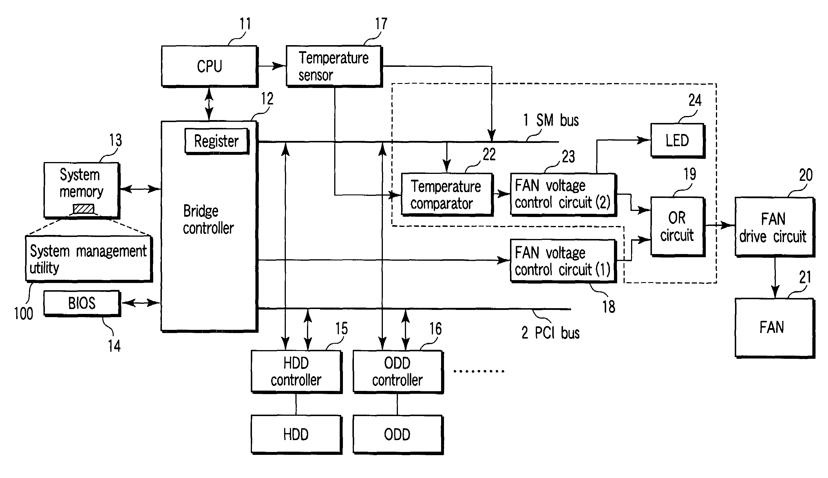
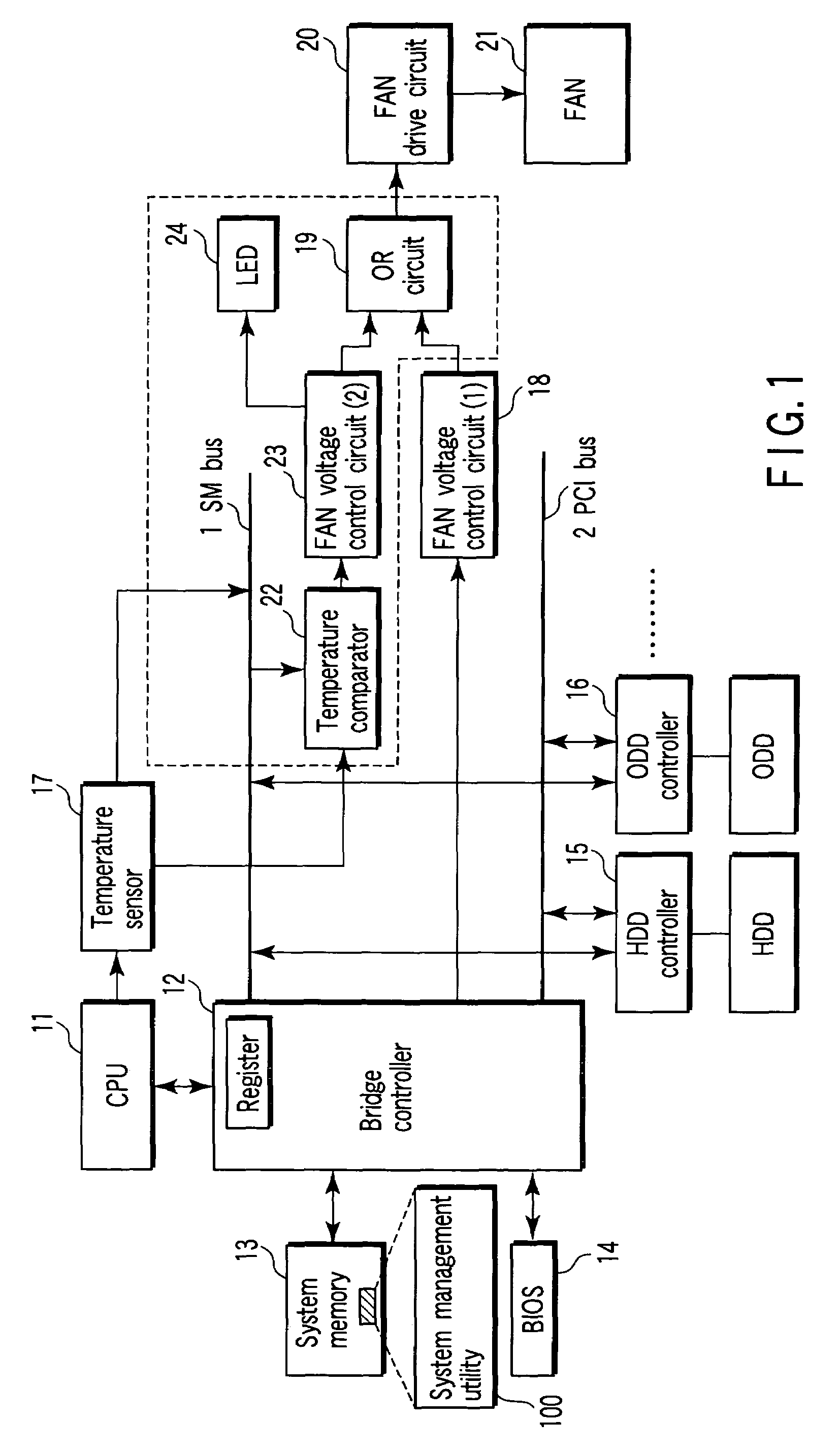
[0016]FIG. 1 shows, in block diagram form, the portion associated with cooling fan control of an electronic apparatus according to an embodiment of the present invention.

[0017]This electronic apparatus, which is, for example, a notebook-type personal computer, is subject to overall control by a CPU 11. In the electronic apparatus, a system management (SM) bus 1 and a peripheral component interconnect (PCI) bus 2 for data transmission and reception are installed. A bridge controller 12 has a bridge function of connecting the SM bus 1 and the PCI bus 2 with the high-speed local bus of the CPU 11.

[0018]A system memory 13 and a BIOS-ROM 14 are connected to the bridge controller 12, which also has the function of controlling access to these components.

[0019]The system memory 13, which is a storage medium that serves as main storage of the electronic apparatus, temporarily stores ...


PUM


Abstract

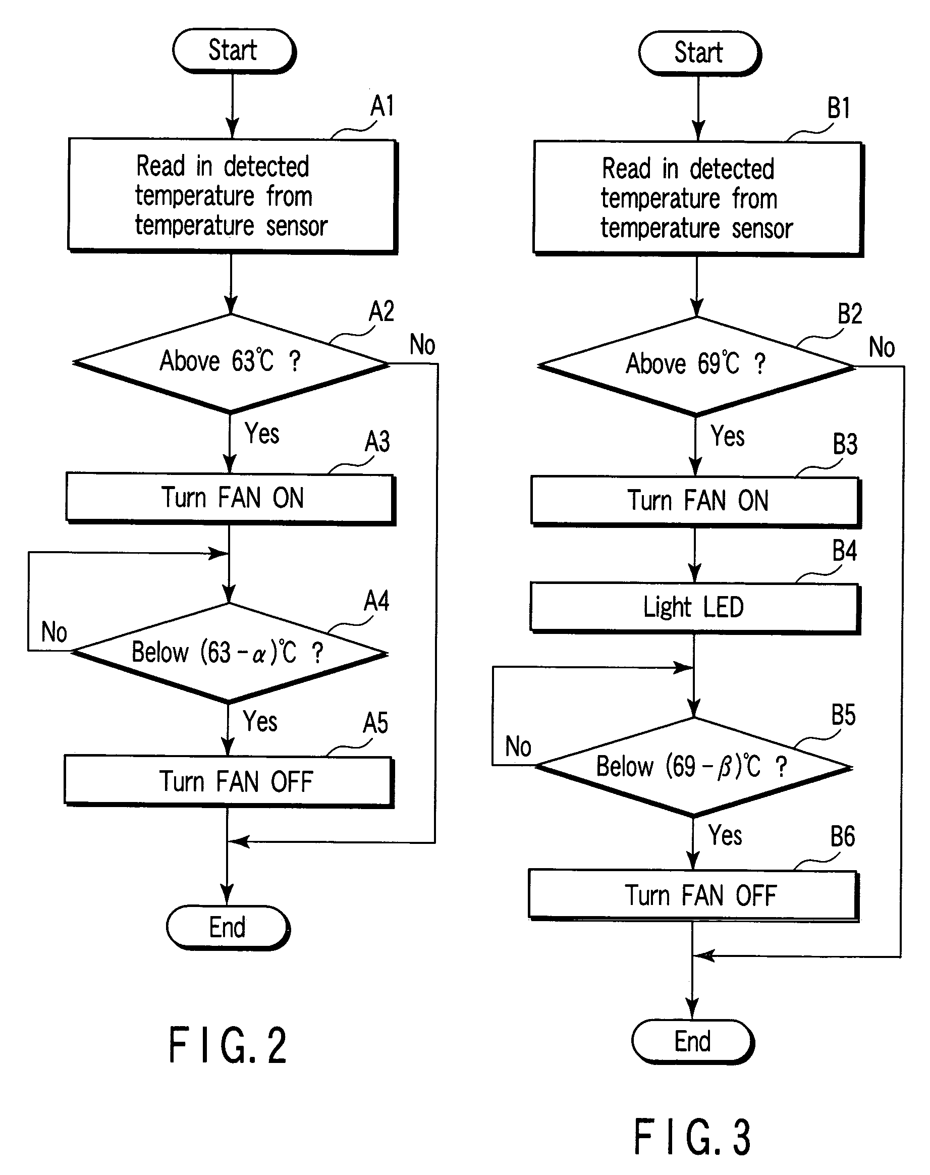
A voltage for driving a cooling fan is usually output from a fan voltage control circuit. Whether to cause the fan voltage control circuit to output the drive voltage or not is controlled by a system management utility (software) and a bridge controller (hardware) on the basis of temperature data from a temperature sensor. To provide for the occurrence of a failure in the system management utility or the bridge controller, a temperature comparator monitors the temperature data from the temperature sensor and instructs a fan voltage control circuit to output a drive voltage for the cooling fan in the case where the temperature rises above a given value.

Description

CROSS-REFERENCE TO RELATED APPLICATIONS[0001]This application is based upon and claims the benefit of priority from prior Japanese Patent Application No. 2003-334179, filed Sep. 25, 2003, the entire contents of which are incorporated herein by reference.BACKGROUND OF THE INVENTION[0002]1. Field of the Invention[0003]The present invention relates to a technique that controls the driving of a cooling fan used in an electronic apparatus such as a personal computer.[0004]2. Description of the Related Art[0005]In recent years, various types of personal computers, such as notebook computers and desktop computers, have come into wide use in offices and homes. In general, with these types of personal computers, a cooling fan is installed in the neighborhood of a central processing unit (CPU) in order to discharge air, the temperature of which has been elevated due to heat generated by the CPU, to the outside of the casing. Control of the cooling fan is carried out on the basis of temperatur...

Claims


Application Information

Patent Timeline
Patent Type & Authority Patents(United States)
IPC IPC(8): G05B5/00G06F1/20H05K7/20
CPCG06F1/206H05K7/20209
Inventor YAMAMOTO, TAKEHIKOSUZUKI
Owner KK TOSHIBA
Learn More