Apparatus for automatically pointing a device at a target

a technology of automatic pointing and target, applied in the field of apparatus, can solve the problems of deficient operation of the device described by the above reference, inconvenient operation, and inability to position the beam on the targ

Inactive Publication Date: 2007-07-17
TSX PRODS
View PDF17 Cites 23 Cited by
  • Summary
  • Abstract
  • Description
  • Claims
  • Application Information

AI Technical Summary

Benefits of technology

[0011]It is still yet another object of the present invention to provide a system that can direct a device like a searchlight and can maintain a direction for the device to keep the device fixed on a target.
[0012]It is also an object of the present invention to provide a system that can point a device at a number of pre-selected targets in a predetermined order, or random order or can sweep between targets in the predetermined or random order.
[0016]It is a further object of the present invention to provide a controller that calculates a position of a target and controls an adjustment device to move a searchlight in response to the position of the target to maintain a beam emitted from the searchlight on the target.
[0017]It is an additional object of the present invention to provide a system that keeps the pointed device fixed on the target so that when the pointed device is activated it will automatically be fixed on the target.
[0019]It is another object of the present invention to provide a controller that can be used with electronic positions from a global positioning source such as GPS or Loran, from a local positioning source such as radio, ultrasonic, or from infrared triangulation, or from pre-recorded electronic positions.

Problems solved by technology

The devices described by the above references are deficient in their operation.
However, this is not helpful in the art as very few applications for searchlights involve platforms that are fixed in position.
Searchlight controllers of the prior art can only position the beam on the target briefly under these conditions and require constant manual adjustment from the user.
This is time consuming and distracts the user from other important tasks.

Method used


Image

  • Apparatus for automatically pointing a device at a target
  • Apparatus for automatically pointing a device at a target
  • Apparatus for automatically pointing a device at a target

Examples


Embodiment Construction

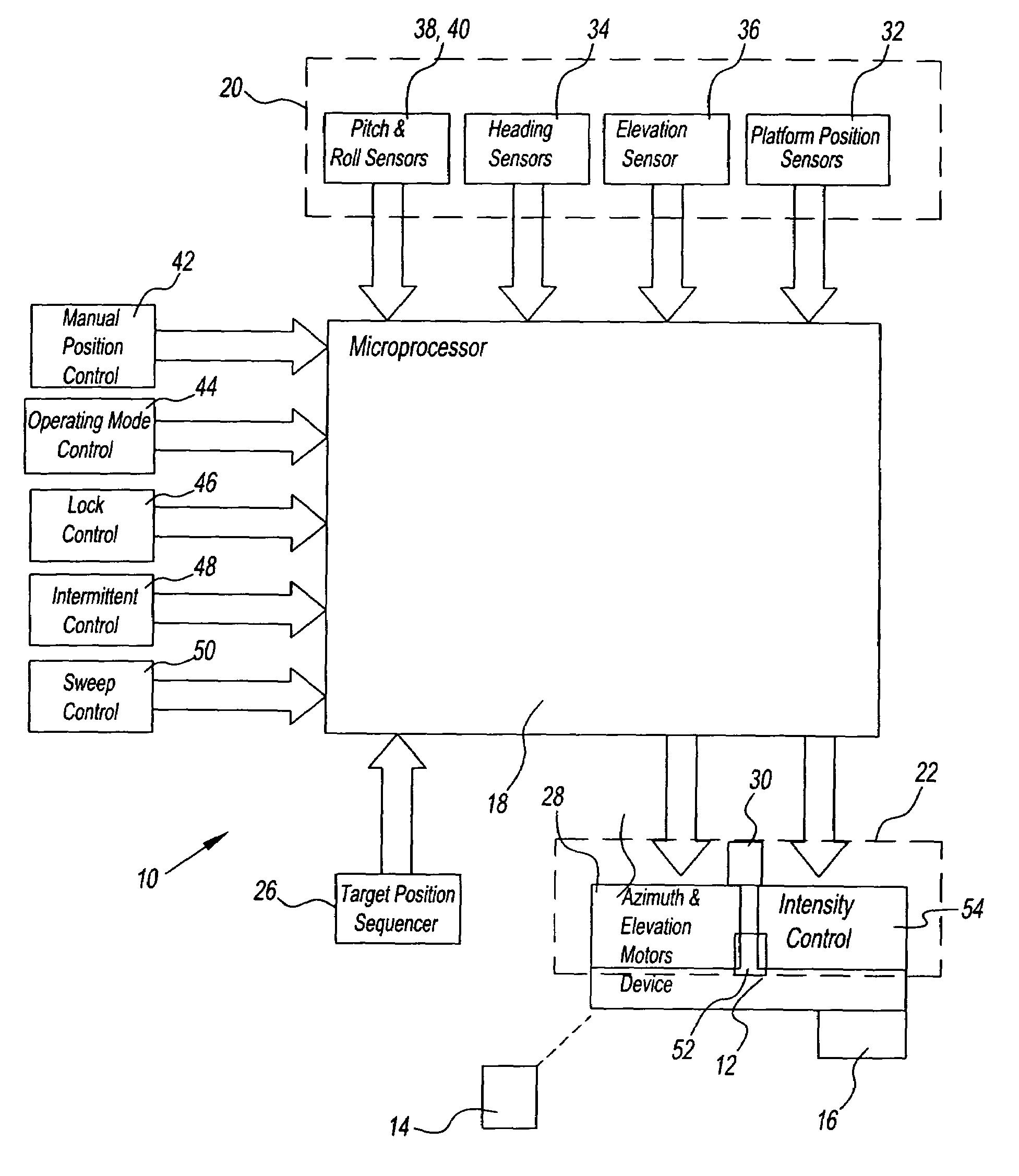
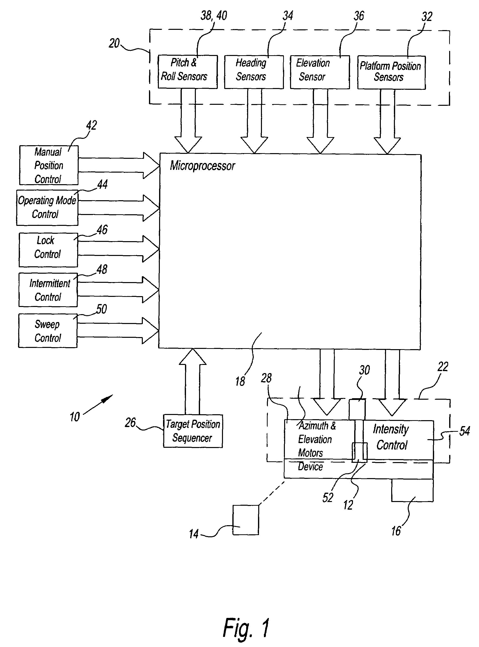
[0030]Referring to the Figures and, in particular, FIG. 1, the present invention is to provide a system 10. The system 10 can maintain a beam of a searchlight 12 fixed to a target 14 regardless of whether the target or a searchlight platform 16 connected to the system are mobile or stationary. Although, the system 10 is shown as being used with the searchlight 12, the system may be used with other electronic devices and in no way is limited to searchlights.

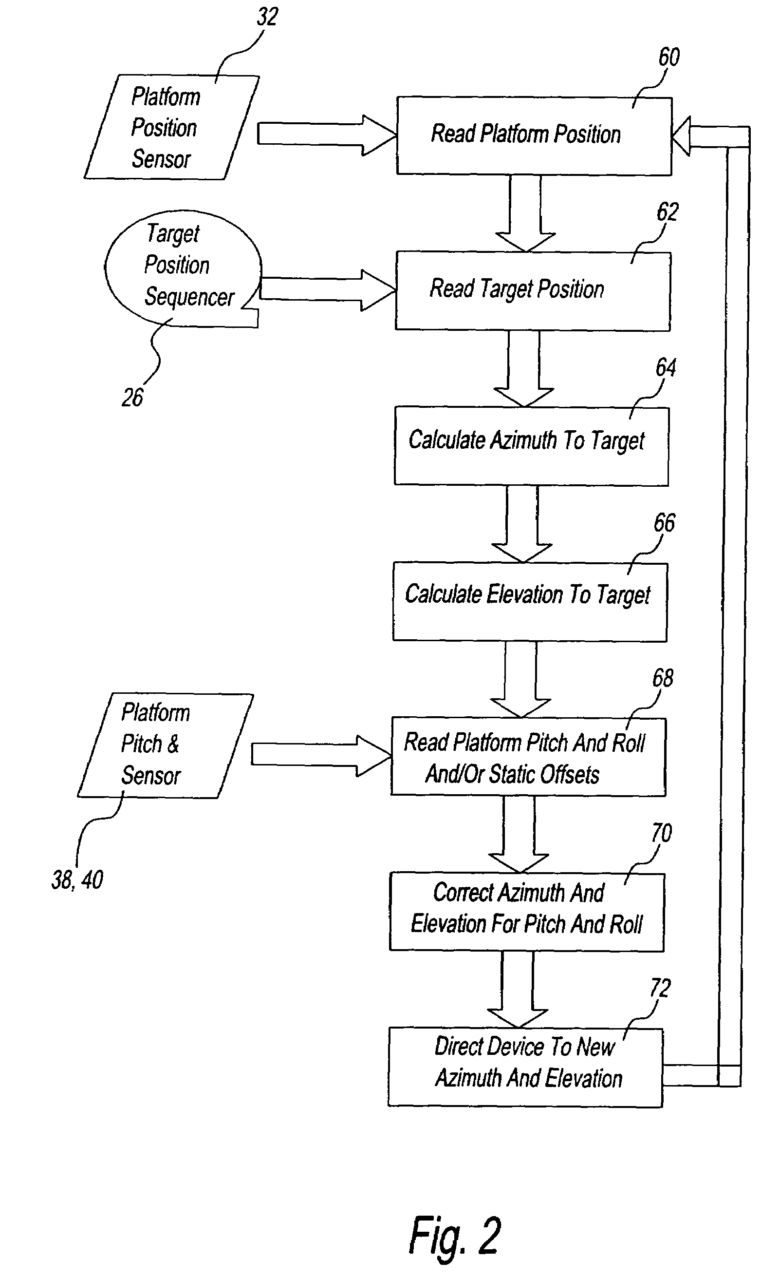
[0031]When activated, the present invention in one embodiment uses a controller 18 to read a latitude reading and a longitude reading of a searchlight's 12 position, and calculates positioning information. The present invention then automatically holds the searchlight 12 and positions the searchlight at a second or a next waypoint.

[0032]The searchlight 12 can then be switched off for extended periods to prevent light adaptation of a pilot and others on the water. When switched back on, the searchlight 12 will be positioned on the ...


PUM


Abstract

A system for pointing a device at a given target has a sensor for sensing a number of positional information points of the target with the sensor relaying the positional information points to a controller. The controller is for computing a directional control information based on the relayed positional information points. The system also has an adjustment device for moving the device in a direction that bears a predetermined relationship to the target in response to the computed direction control information. The target moves and the sensor senses the positional information of the target and the sensor relays the positional information to the controller with the controller computing the directional control information to control the adjustment device. The adjustment device points the device at the target.

Description

CROSS REFERENCE TO RELATED APPLICATIONS[0001]This application claims priority to U.S. Provisional Patent Application Ser. No. 60 / 513,813 filed on Oct. 23, 2003, which is herein incorporated by reference in its entirety.BACKGROUND OF THE INVENTION[0002]1. Field of the Invention[0003]The present invention relates to an apparatus that automatically points a device in a direction toward a target. More particularly, the present invention relates to an apparatus that automatically senses a location of the target, and of the device to be pointed and based upon those locations moves a searchlight using an adjustment device in the direction toward the target.[0004]2. Description of the Related Art[0005]Technology exists for manual remote control for positioning a searchlight through mechanical, wired and wireless electrical means. Such known patents include U.S. Pat. No. 3,979,649 to Persha, U.S. Pat. No. 5,490,046 to Gohl, et al., U.S. Pat. No. 5,673,989 to Gohl, et al., and U.S. Pat. No. 6...

Claims


Application Information

Patent Timeline
Patent Type & Authority Patents(United States)
IPC IPC(8): G01S13/00A61BB64C1/00F41A27/28
CPCF41A27/28F41G5/14G05D3/12
Inventor VOGEL, DAVID A.JOHNSON, ERIK W.MCCULLEY, RICHARD L.
Owner TSX PRODS
Why Eureka
Try Eureka