Thermal printer with quick-release printhead assembly

a printing head and assembly technology, applied in the field of printing head assemblies, can solve the problems of difficult replacement of the printhead by the end user, difficult use of traditional brackets to attach the printhead to the housing or sub-frame of the printer, and often the problem of direct attachment of the printhead to electronic or mechanical components, etc., to achieve the effect of convenient installation or replacement of the printing componen

Active Publication Date: 2007-07-17
ZEBRA TECH CORP
View PDF6 Cites 14 Cited by
  • Summary
  • Abstract
  • Description
  • Claims
  • Application Information

AI Technical Summary

Benefits of technology

[0008]The invented quick-release printhead assembly allows for the convenient installation or replacement of a printing component, e.g. a thermal printhead or combination of thermal printhead and heat sink, within a thermal printer by providing a push-lock retention feature fixed within the housing of a printer body and providing a printing component that is correspondingly sized and shaped to be releasably received into the retention feature. The retention feature holds the printhead in a fixed position relative to the housing and, therefore, also relative to the platen of the printer during operation of the printer.
[0009]The retention feature is preferably molded directly into a portion of the printer housing, thereby eliminating the need to produce or use attachment brackets or other hardware to affix the printing component within the printer. Alternatively, the retention feature may comprise one or more brackets or similar hardware mounted to the printer housing.
[0011]According to another embodiment, the printing component may be more precisely positioned adjacent to the platen and associated print media of the printer by incorporating a biasing member within the printer such that the biasing member contacts the printing component upon fixing the printing component in the retention feature so that bias is maintained on the printing component when installed in the retention feature.
[0014]According to another embodiment, the invention encompasses a thermal printer with a readily-replaceable printing component and method of installing the printing component, the printer having a printer housing with a component retention feature attached to or integrally molded therein, a platen that mates with the housing, and a printing component, wherein the printing component is releasably fixed within the retention feature of the housing. The thermal printer may comprise any combination of the advantageous features discussed with regard to the printing component, including a biasing member for biasing the printhead toward the platen. In addition, the thermal printer may include components that improve upon the general performance of the printer, including a microprocessor in electronic communication with the printhead, an electromotive device in mechanical communication with the platen, a media receptacle within the housing for holding a supply of print media, and further including additional features generally known in the art of thermal printers.
[0015]The quick-release printhead assembly design provides several advantages over printhead assemblies of the past. By use of a push-lock feature, such as a deflecting lock tab, the printhead or combined printing component is easily installed within the retention feature without the need for tools. By incorporating a release feature into the retention feature, the printing component may be conveniently, easily, and quickly removed or replaced. The optional biasing member automatically provides a biasing force against the installed printing component, thereby providing optimal placement of the printhead without the need to adjust brackets or other hardware. These and other advantages will be evident to one of skill in the art after review of this disclosure.

Problems solved by technology

Direct attachment of the printhead to electronic or mechanical components is often problematic due to added process steps required to attach or replace the printhead.
Similarly, the use of traditional brackets to attach a printhead to the housing or sub-frame of a printer is problematic because of added complexity and production and assembly costs associated with fixing a printhead within the brackets.
Further, replacement of a printhead typically involves removal of screws, brackets, or other hardware used to hold the printhead in place, thereby making it difficult for an end user to replace a printhead.

Method used


Image

  • Thermal printer with quick-release printhead assembly
  • Thermal printer with quick-release printhead assembly
  • Thermal printer with quick-release printhead assembly

Examples


Embodiment Construction

[0024]The present invention now will be described more fully hereinafter with reference to the accompanying drawings, in which some, but not all embodiments of the invention are shown. Indeed, the invention may be embodied in many different forms and should not be construed as limited to the embodiments set forth herein; rather, these embodiments are provided so that this disclosure will satisfy applicable legal requirements. Like numbers refer to like elements throughout.

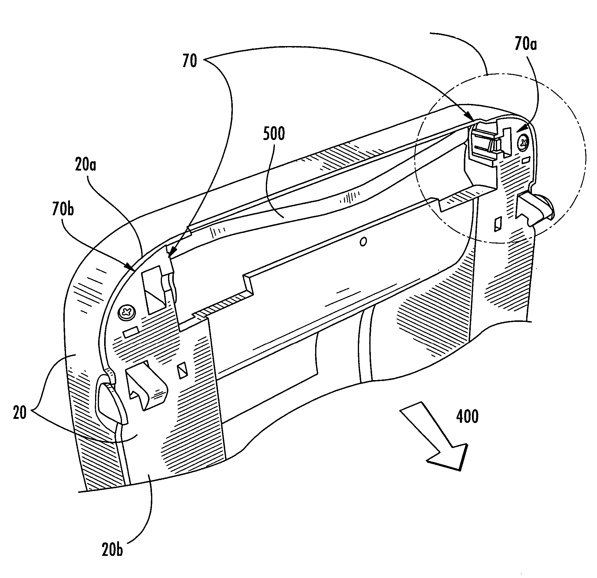
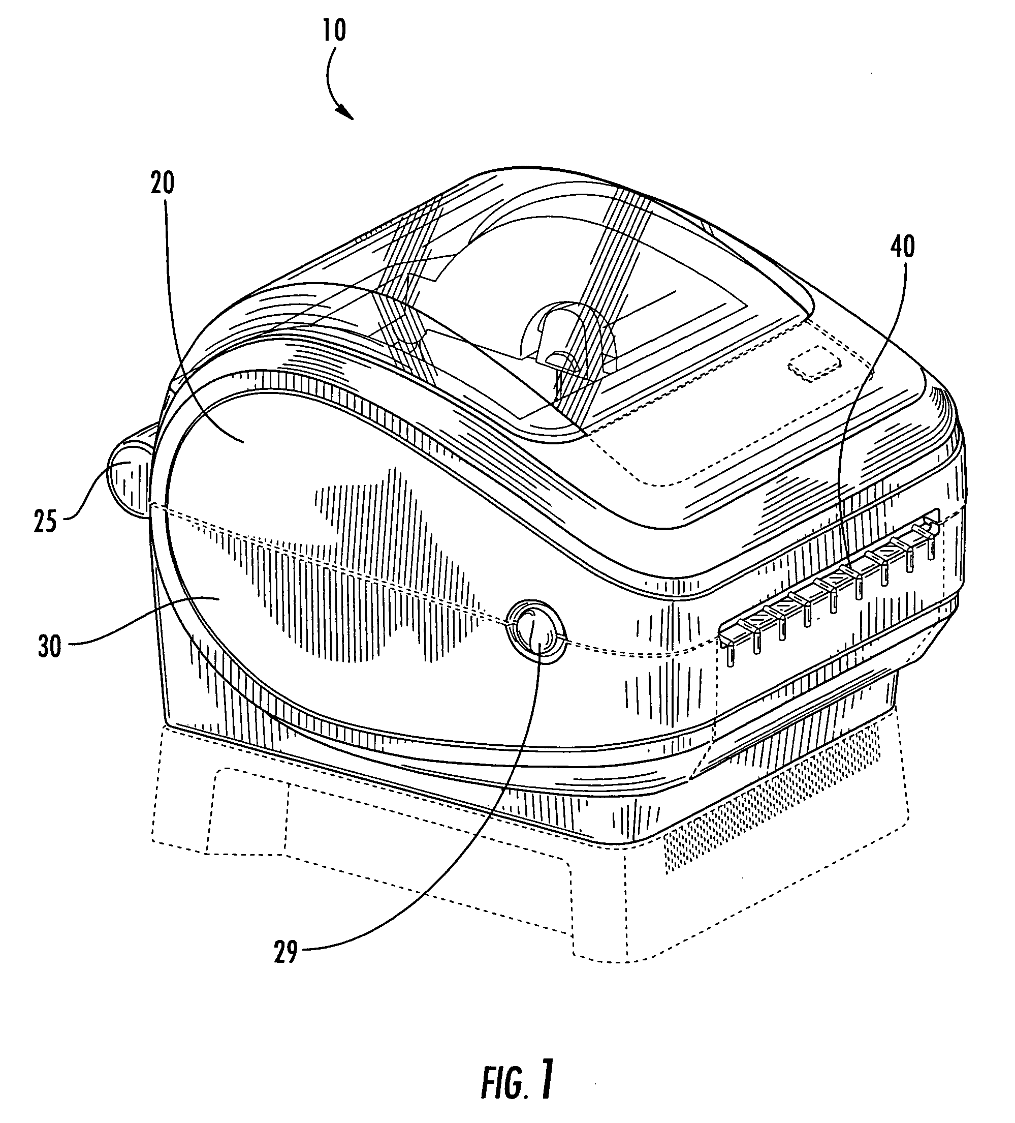
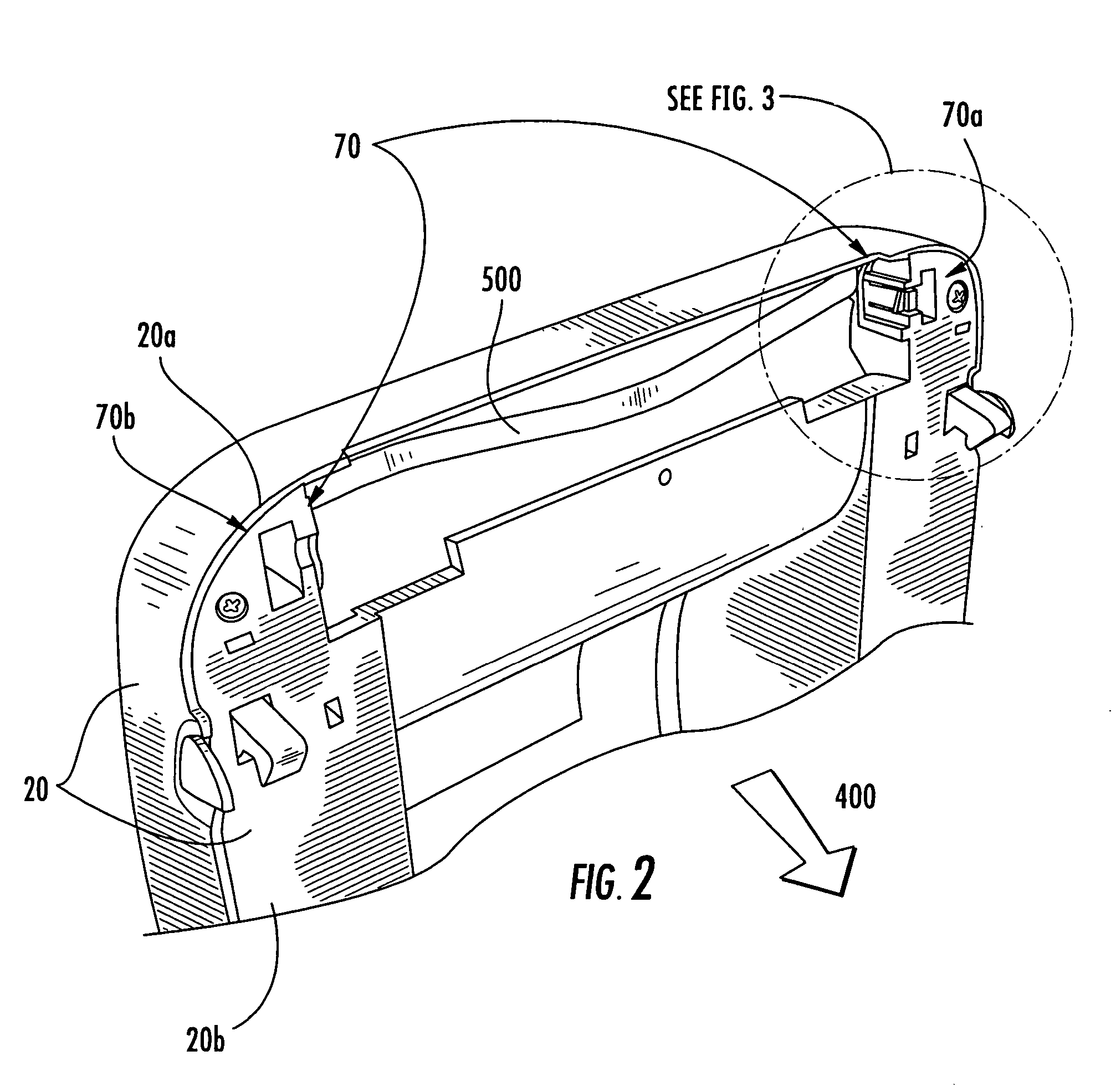
[0025]FIGS. 1–9 are directed to an exemplary embodiment of the invented printhead assembly and to an exemplary thermal printer that incorporates the assembly. The exemplary embodiment and further embodiments are described herein without detailed description of well-known structures associated with thermal printers, such as drive mechanisms, print media, print media handlers, and electronic or microprocessor controllers, as the operation of structures within the printer are readily understood by those of skill in th...


PUM


Abstract

A quick-release printhead mounting assembly and thermal printer incorporating same, including a printing component, a printer housing, and, a component retention feature attached to or molded into the printer housing adapted for receiving and releasably fixing the printing component to the housing. The retention feature holds the printhead in a fixed position relative to the housing and, therefore, also relative to the platen of the printer. The printing component is advantageously a printhead, such as a thermal printhead, or the combination of a thermal printhead and a heat sink.

Description

BACKGROUND OF THE INVENTION[0001]1. Field of the Invention[0002]The present invention relates to printhead assemblies for use in thermal printers. More particularly, the invention relates to the assembly or attachment of thermal printheads within thermal printer housings.[0003]2. Description of Related Art[0004]Thermal printers require that a thermal printhead be oriented and maintained in close proximity to print media during printing so that the printhead may heat a thermal transfer ribbon to cause coloration to be transferred to the print media or, alternatively, to directly heat regions of thermal contact media, thereby causing the contact media to change color. The printheads are typically joined with heat sinks to provide for heat dissipation, and the joined parts are typically positioned within a printer housing such that a print media may be moved within the housing relative to the printhead. Alternatively, the printhead may be movable within the housing with respect to the ...

Claims


Application Information

Patent Timeline
Patent Type & Authority Patents(United States)
IPC IPC(8): B41J25/304B41J25/34
CPCB41J2/325B41J2202/31
Inventor SMOLENSKI, LAWRENCE EDWARDMASTINICK, PHILIP ALAN
Owner ZEBRA TECH CORP
Why Eureka
Try Eureka