Method and apparatus for displaying three-dimensional stereo image using light deflector

a three-dimensional stereo image and light deflector technology, applied in the field of three-dimensional stereo image display methods and apparatuses, can solve the problems of large 3d image display apparatuses with increased cost, and the inability to allow several people to enjoy high-resolution 3d images, and achieve the effect of satisfying image quality

Inactive Publication Date: 2007-07-17
RICOH KK
View PDF42 Cites 90 Cited by
  • Summary
  • Abstract
  • Description
  • Claims
  • Application Information

AI Technical Summary

Benefits of technology

[0013]The present invention also provides a technique for displaying a three-dimensional stereo image observable at multiple viewpoints with a satisfactory image quality.

Problems solved by technology

However, this technique causes the 3D image display apparatus to become large with increased cost.
Actually, a technique of allowing several people to enjoy high-resolution 3D images has not been realized.

Method used


Image

  • Method and apparatus for displaying three-dimensional stereo image using light deflector
  • Method and apparatus for displaying three-dimensional stereo image using light deflector
  • Method and apparatus for displaying three-dimensional stereo image using light deflector

Examples


example 3

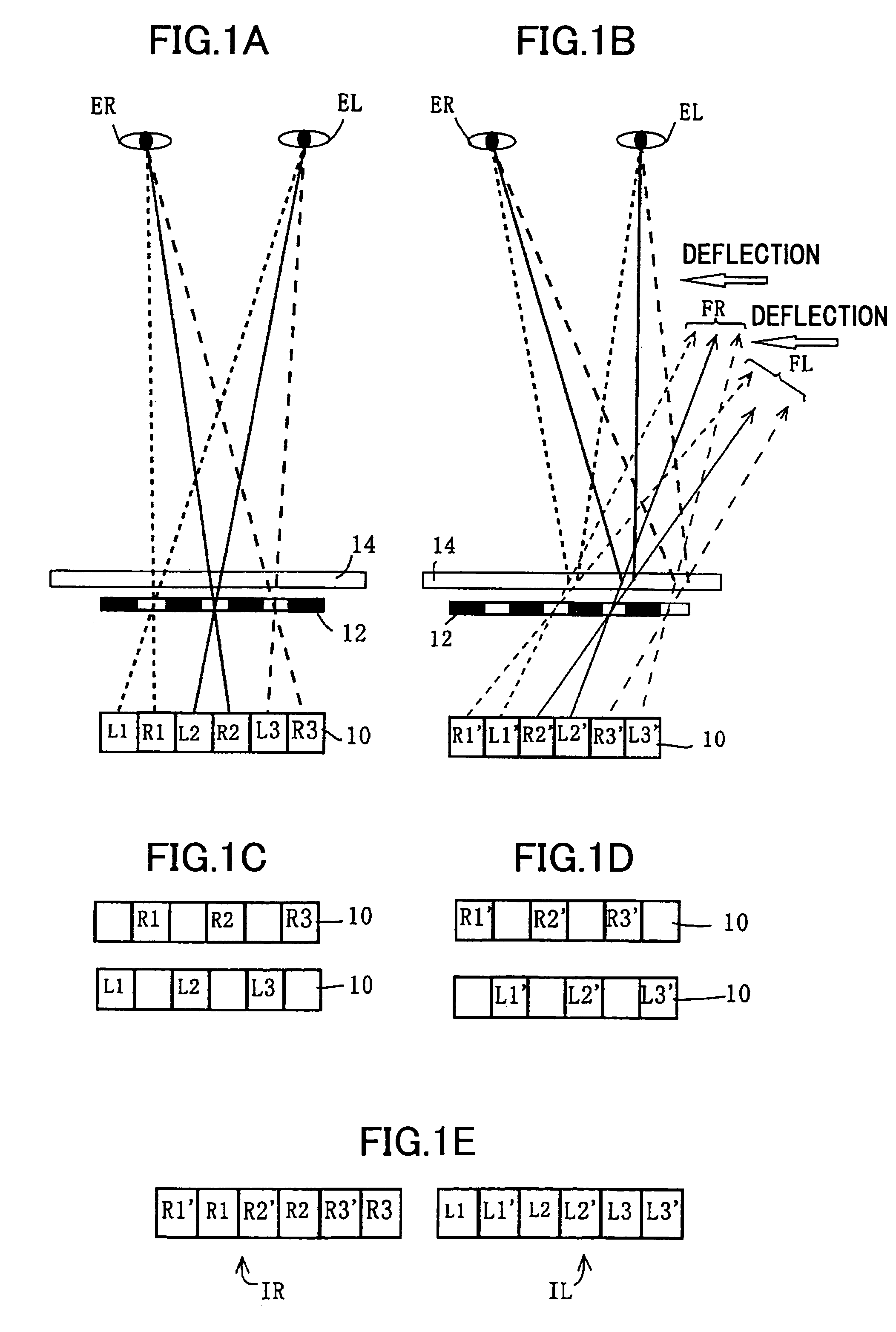
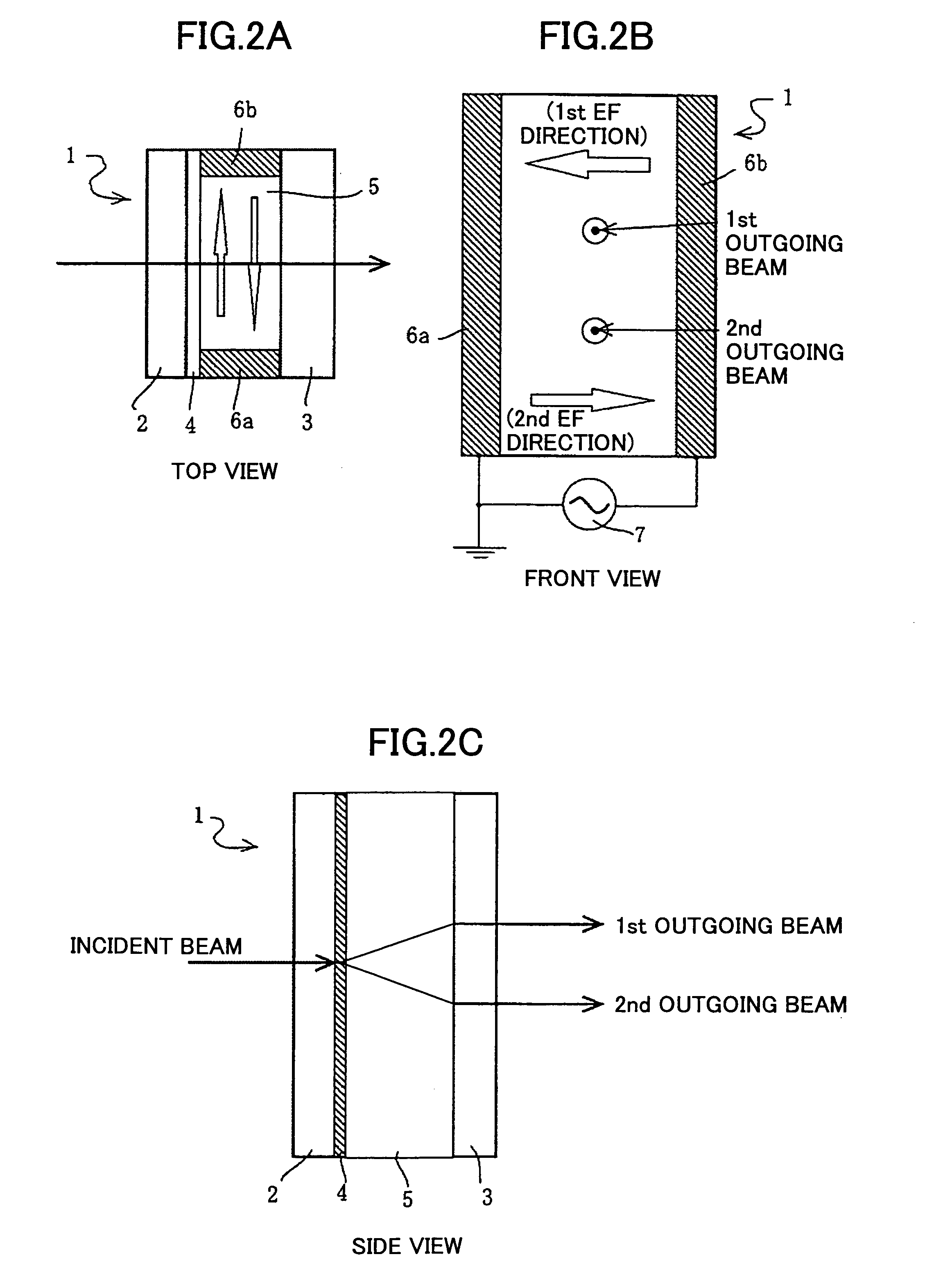
[0161]A deflecting device 14 of still another arrangement is added to the basic structure.

[0162]A silica grass substrate is dry-etched to form a saw-tooth surface with a tilt angle of 0.5 degrees and a pitch of 500 μm. Then, an ITO is sputtered on the saw-tooth surface up to a thickness of 2000 Å to form an ITO electrode. Then, the silica glass substrate with the ITO electrode is coated with polyamide aligning material AL3046 up to the thickness of 800 Å. The AL3046 layer is rubbed such that the homogeneously stabilized direction becomes perpendicular to the slope of the saw-tooth surface. Another glass substrate with an ITO electrode having a flat surface is bonded to the silica glass substrate with the saw-tooth surface using a bead-mixed adhesive, such that the smaller thickness of the liquid crystal layer becomes 1.5 μm. A ferroelectric liquid crystal (R5002 manufactured by Clariant) is injected by capillary phenomena such that the injecting direction is along the saw-tooth shap...

example 5

[0167]A deflecting device 14 of yet another arrangement is added to the basic structure.

[0168]An ITO strip-electrode illustrated in FIG. 8B is formed on one of the two transparent glass substrates. The strip pattern has a width of 47 μm, and a pitch of 50 μm, and the strips of the ITO electrode are connected by high-resistance wires. Another ITO electrode is formed over the entire surface of the other glass substrate.

[0169]An aligning film with a thickness of about 800 Å is formed over each of the glass substrates on the side of ITO electrode by applying a polyamide group material (AL3046-R31 manufactured by JSR Corporation) company) by spin coating. After the annealing process, rubbing is carried out on the strips of the ITO electrode in a perpendicular direction to the strips.

[0170]The two glass substrates are held facing each other, and bonded together with a PET Mylar (registered trademark) with a thickness of 20 μm inserted as a spacer between them. After pressurization, the tw...

example 6

[0176]A lenticular array is used as the left and right image separator in place of the striped barrier in the basic structure shown in FIG. 9. This substituted basic structure is referred to as the second basic structure. The lenticular lens array has a lens pitch of about 0.2 mm, and is positioned at 1.6 mm distant from the liquid crystal display panel (image display device).

[0177]The deflecting device used in Example 1 is added to this second basic structure, and a three-dimensional image is observed in the same manner as in Example 1. Then, a brighter three-dimensional image was observed, as compared with Example 1.

[0178]As has been described above, the three-dimensional image display technique according to the first embodiment can improve the horizontal resolution of the displayed three-dimensional image.

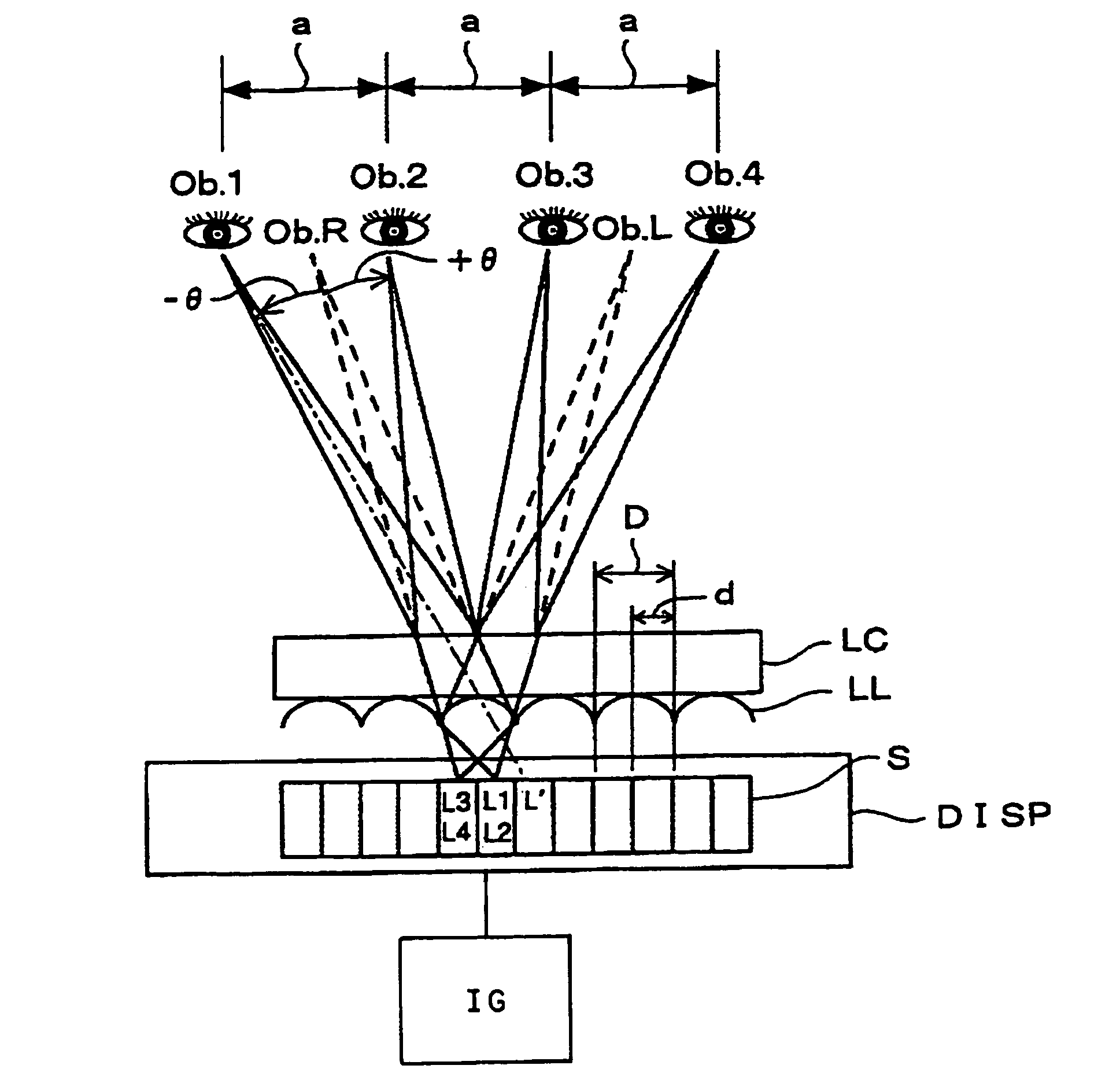
[0179]Next, the second embodiment of the present invention is described. In the second embodiment, a multiview 3D image display apparatus is provided, which allows a three-dimen...


PUM


Abstract

In a method for displaying a three-dimensional stereo image, a left-eye image defined by multiple left-eye strip pixels and a right-eye image defined by multiple right-eye strip pixels are displayed such that the left-eye pixels and the right-eye pixels are arranged alternately from the left to the right in a width direction. The left-eye image and the right-eye image are guided separately to the left eye and the right eye of an observer. Then, the left-eye image and the right-eye image are shifted by one pixel in an oscillating manner, and the left-eye image and the right-eye image are deflected synchronized with the one-pixel shifting operation.

Description

BACKGROUND OF THE INVENTION[0001]1. Field of the Invention[0002]The present invention generally relates to a method and apparatus for displaying a three-dimensional (3D) stereo image, and more particularly to a 3D stereo image display technique making use of a light deflector to allow an observer or a viewer to perceive a three-dimensional image without wearing special glasses.[0003]2. Description of Related Art[0004]Stereoscopic sense is derived from the mechanism of binocular parallax, where images reflected in the left eye and the right eye differ from each other. Various studies have been made on three-dimensional (3D) image display apparatuses. For example, JP 53-80114A discloses a stereo television apparatus that requires viewers to wear special glasses (using a left-eye lens and a right-eye lens with 90-degree shifted polarization).[0005]Other types of 3D image display apparatuses that do not require special glasses have also been developed. For example, JP 7-181429A disclose...

Claims


Application Information

Patent Timeline
Patent Type & Authority Patents(United States)
IPC IPC(8): G02B27/22H04N13/04H04N13/00
CPCG02B27/2235G02B27/2242H04N13/0404H04N13/0409H04N13/0454G02B30/35G02B30/36H04N13/305H04N13/31H04N13/359
Inventor KOBAYASHI, MASANORITOKITA, TOSHIAKIMATSUKI, YUMISUGIMOTO, HIROYUKI
Owner RICOH KK
Why Eureka
Try Eureka