Electronics cabinet with internal air-to-air heat exchanger

a technology of air-to-air heat exchanger and electronic cabinet, which is applied in the direction of electrical apparatus casing/cabinet/drawer, cooling/ventilation/heating modification, instruments, etc., can solve the problems of separate air-to-air heat exchanger, component overheating and failure, and significant heat generation during operation

Active Publication Date: 2007-07-17
UTSTARCOM INC
View PDF9 Cites 60 Cited by
  • Summary
  • Abstract
  • Description
  • Claims
  • Application Information

AI Technical Summary

Benefits of technology

[0008]Electronic circuits which are located inside a cabinet or enclosure generate heat that must be dissipated. The present invention provides an internal heat exchanger arrangement within the cabinet that not only cools the cabinet but also provides isolation of outside (ambient) air from the air in the interior of the cabinet so that no pollutants, dust or humidity enters the interior of the cabinet where the electronics components are located.

Problems solved by technology

These printed circuit boards and / or cards incorporate numerous semiconductor-based electronic components such as microprocessors and integrated circuit chips, which generate significant amounts of heat during operation.
Accordingly, the heat generated by such components must be removed from the enclosure they are housed in or else the components will overheat and fail.
A separate air-to-air heat exchanger, such as the HXi Series air-to-air heat exchanger from Thermacore, is expensive and increases the size of the overall system, and thus does not fully address the problems in the art.

Method used


Image

  • Electronics cabinet with internal air-to-air heat exchanger
  • Electronics cabinet with internal air-to-air heat exchanger
  • Electronics cabinet with internal air-to-air heat exchanger

Examples


Embodiment Construction

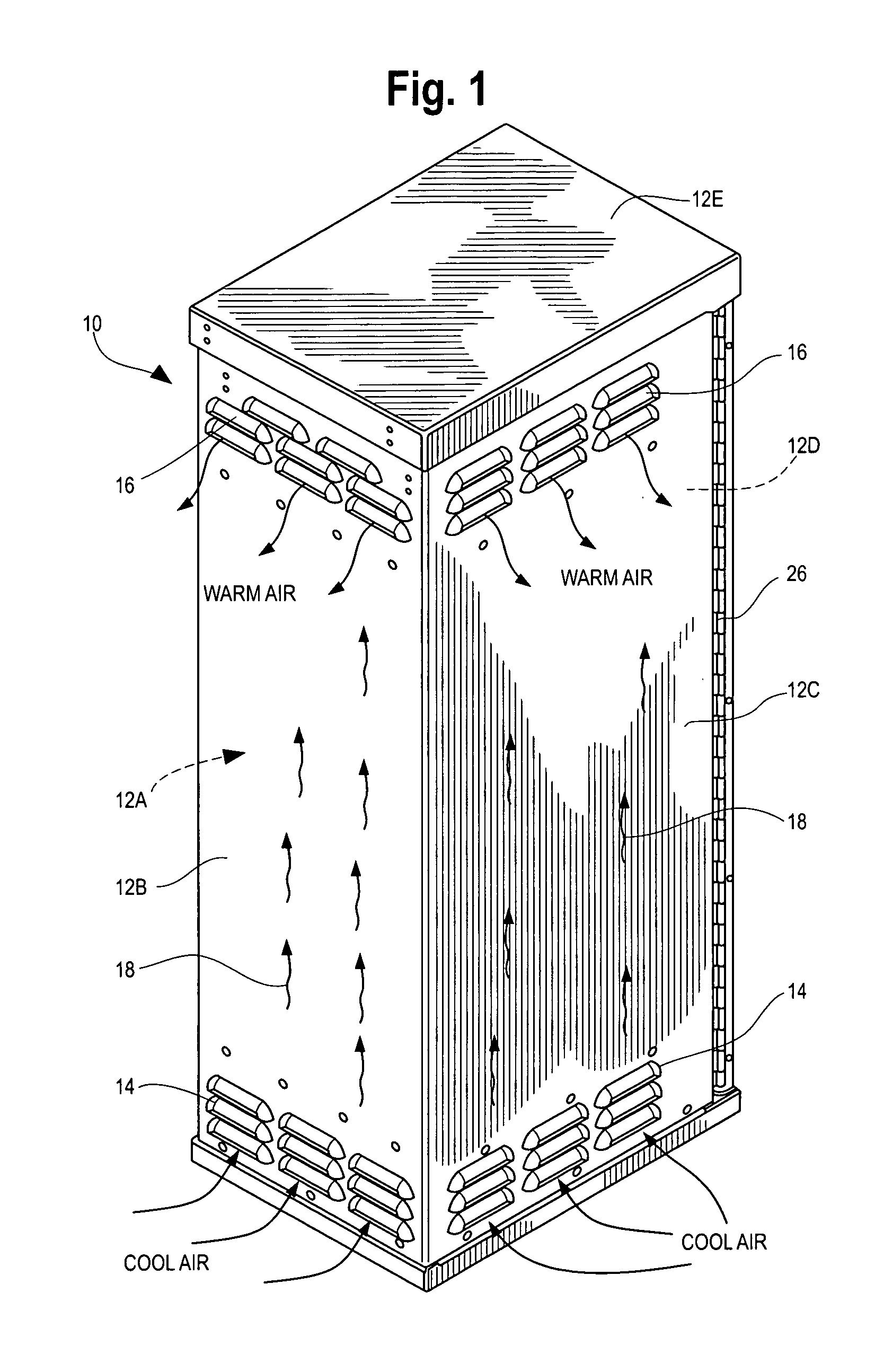
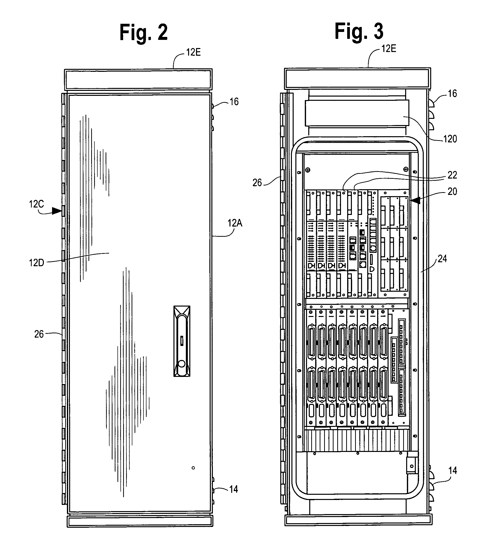
[0024]Referring now generally to FIGS. 1–4, FIG. 1 is a perspective view of a cabinet 10 enclosing electronic components (see FIG. 3), showing the outer panels 12 or “skin” forming the periphery of the cabinet 10. The panels 12 include the three side panels 12A, 12B and 12C, a front door 12D which is facing away from the viewer in FIG. 1, and a top panel 12E. The side panels 12A–C include lower air intake vents 14 where relatively cooler air is introduced into the cabinet, and more particularly to narrow air gap or space that exists between the skins 12A–C and the outer surface of a plurality of air-to-air heat exchanger wall elements described below. The heat exchanger walls block ambient air from entering the interior of the cabinet where the electronic components are housed. The side walls also include upper exhaust vents 16 where relatively warmer air is removed from the cabinet.

[0025]The arrows 18 in FIG. 1 show the air flow path for ambient air. The air flow path 18 is achieve...


PUM


Abstract

An enclosure has a set of panels forming an outer peripheral skin. A heat exchanger wall is placed within the panels. A first fan arrangement circulates ambient air into a space within the panels and along the exterior surface of the heat exchanger wall and back into the environment. A second fan arrangement circulates air contained within the enclosure against the interior surface of the heat exchanger wall. Heat is transferred through the heat exchanger wall to the ambient air circulated by the first fan. An inner wall is placed adjacent to the interior surface of the heat exchanger wall. The space between the inner wall and the heat exchanger wall forms a space for the air within the interior of the enclosure to circulate by the second fan. The heat exchanger wall provides a barrier isolating the ambient air from the air within the enclosure, preventing dust, humidity and pollutants to enter into the interior of the cabinet in the space surrounding the electronic components.

Description

BACKGROUND[0001]1. Field of Invention[0002]This invention relates generally to the subject of methods and systems of providing cooling to a cabinet or enclosure. The cooling is needed because the cabinet contains electronic components that generate heat. Such cabinets are used in a variety of devices, for example servers, and switching and routing devices used in telecommunications, and in Telephone Company, Internet service provider, and computer network applications. More particularly, the invention relates to a cabinet design that includes an internal air-to-air heat exchanger and fan arrangement that provides cooling for the cabinet while simultaneously preventing dust, humidity or pollutants from the environment from entering the interior of the cabinet where the electronic components are located. This feature is particularly important in the application of electronics cabinets used in outside environments, such as in the case of some types of switching and networking equipment...

Claims


Application Information

Patent Timeline
Patent Type & Authority Patents(United States)
IPC IPC(8): G06F1/20
CPCG06F1/181G06F1/20H05K7/20736
Inventor MORRELL, EDWARD ALBERT
Owner UTSTARCOM INC
Why Eureka
Try Eureka