
System and method for providing sealing arrangement in X-ray tube

a technology of sealing arrangement and x-ray tube, which is applied in the direction of x-ray tube, x-ray tube gas control, sliding contact bearing, etc., can solve the problems of shortening the operating life, reducing performance, and increasing wear and tear

Inactive Publication Date: 2007-07-17
GENERAL ELECTRIC CO
View PDF5 Cites 2 Cited by
  • Summary
  • Abstract
  • Description
  • Claims
  • Application Information

AI Technical Summary

Benefits of technology

The solution effectively stabilizes the liquid metal lubricant flow and prevents leakage, enhancing the operational life and reducing noise by up to 10 dB, even at high gantry loads and anode rotation speeds.

Problems solved by technology

This causes increased wear and tear of the X-ray tube, which can result in reduced performance.
Such leakage can cause electrical (high voltage) instability in the X-ray tube, thereby shortening operating life.
However, the axial interface may not perform adequately at higher loads and speeds.

Method used


Image

  • System and method for providing sealing arrangement in X-ray tube
  • System and method for providing sealing arrangement in X-ray tube
  • System and method for providing sealing arrangement in X-ray tube

Examples


Embodiment Construction

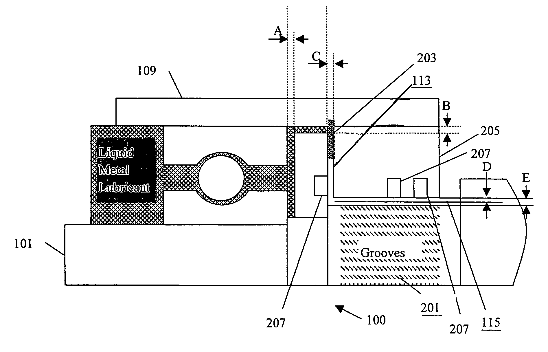
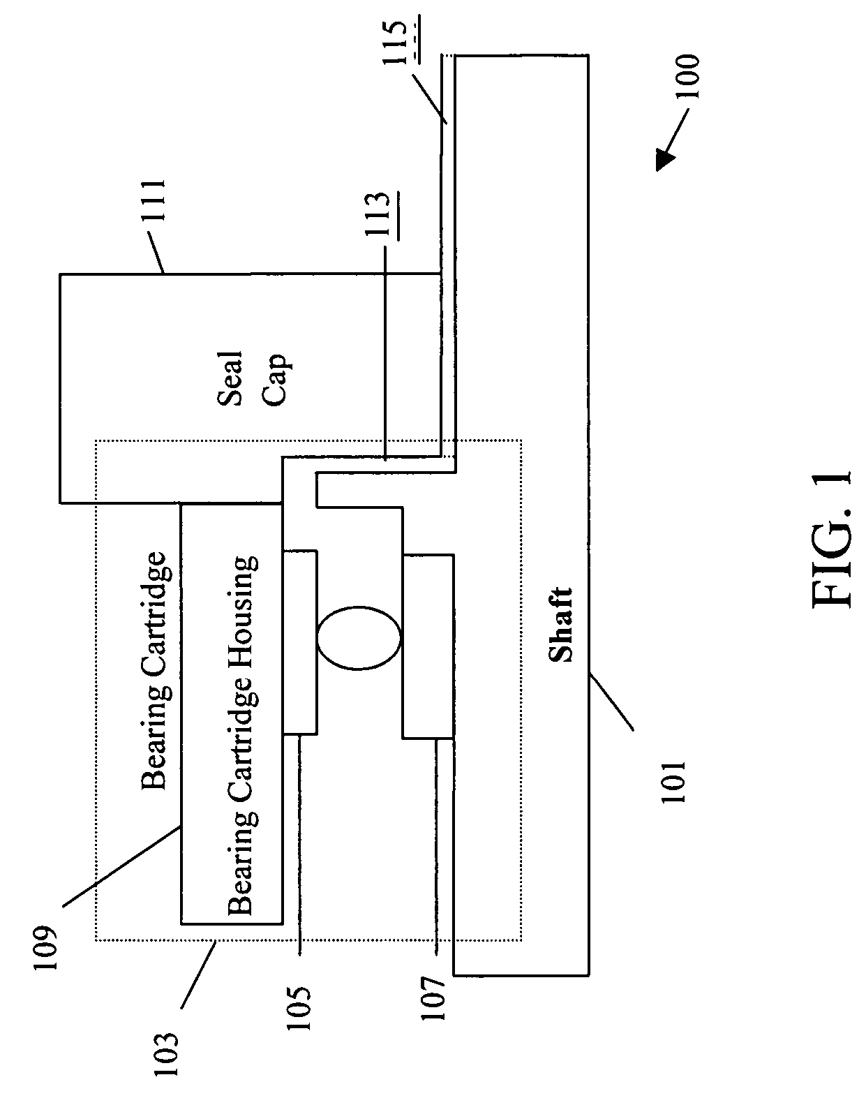
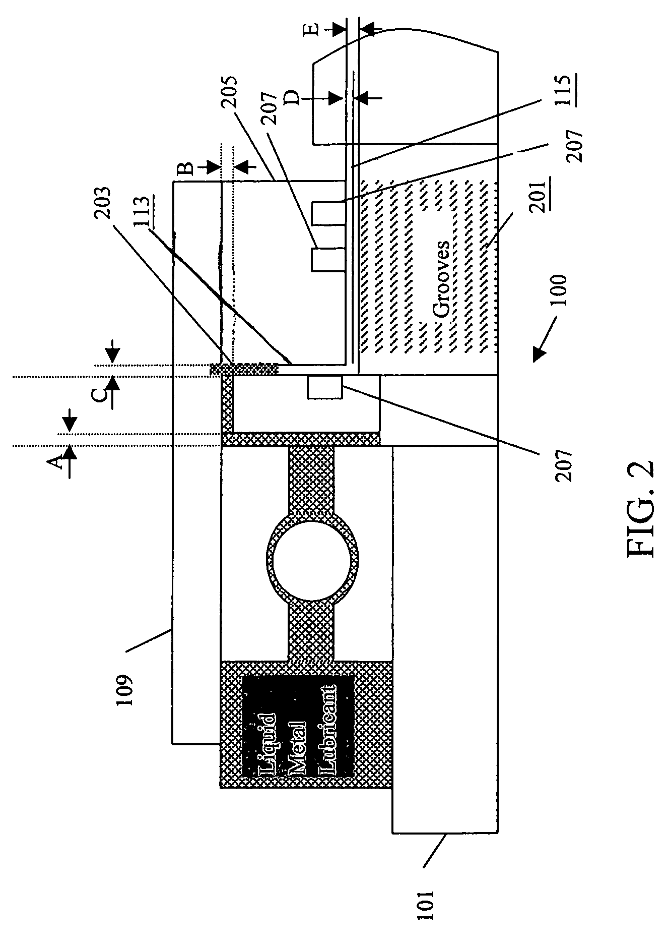
[0012]In various embodiments of the present invention, a rotating device is provided. The rotating device includes a rotating portion having a plurality of ball bearings and a liquid metal for at least one of lubricating and cooling the ball bearings. The liquid metal is contained within a housing having the ball bearings therein. The rotating device further includes a sealing portion formed by a liquid metal vacuum interface, including, for example, a liquid metal vacuum / ambient fluid interface configured to resist or prevent flow of the liquid metal from the housing to a vacuum / ambient portion. In an exemplary embodiment, the rotating device is an X-ray tube operating in a vacuum environment.

[0013]FIG. 1 is a block diagram showing an X-ray tube in accordance with the exemplary embodiment. X-ray tube 100 operates in a vacuum environment and includes a shaft 101, a bearing cartridge 103 having a bearing cartridge housing 109. Further, X-ray tube 100 includes a seal cap 111, an axial...


PUM


Abstract

A system and method for providing a sealing arrangement in an X-ray tube are provided. The X-ray tube includes a rotating portion having a plurality of ball bearings and a liquid metal within a housing having the ball bearings therein. The rotating portion is configured to rotate an anode. The X-ray tube further includes a sealing portion formed by a liquid metal vacuum interface configured in a radial direction to resist flow of liquid metal from the housing to a vacuum portion.

Description

BACKGROUND OF THE INVENTION[0001]The present invention relates generally to X-ray tubes, and more particularly, to lubricant sealing within X-ray tube bearing assemblies.[0002]Various techniques for manufacturing a rotary anode type X-ray tube are known. The rotary anode type X-ray tube typically includes generally, a vacuum chamber, a rotating shaft and a stator. A bearing cartridge also typically is provided between the rotating shaft and the stator and includes a roller type bearing assembly. The rotating shaft is attached to the anode that is rotated using the shaft. The anode includes a target that heats to high temperatures during the operation of the X-ray tube. This is due to the constant impingement of electrons on the surface of the target-bearing cartridge, which accumulates heat generated at the target. As a result, there is a temperature inequality between the rotating shaft and the stator. This causes increased wear and tear of the X-ray tube, which can result in reduc...

Claims


Application Information

Patent Timeline
Patent Type & Authority Patents(United States)
IPC IPC(8): H01J35/00
CPCH01J35/101F16C17/026F16C33/109H01J2235/1086H01J2235/20F16C2380/16H01J35/1024
Inventor VADARI, HARITHTURAGA, RAMTIWARI, MAYANKGOWDA, HOMBEVERMILYEA, MARK ERNESTDAHAN, FREDERICSAINT MARTIN, THOMAS
Owner GENERAL ELECTRIC CO
Learn More