
Logic analyzer having a disassembler employing symbol table information for identifying op-codes

a logic analyzer and symbol table technology, applied in the field of disassembly of logic analyzers, can solve problems such as the inability of engineers to understand the exact operation of the system, and the inability of engineers to write software in assembly languag

Inactive Publication Date: 2007-07-17
TEKTRONIX INC
View PDF20 Cites 5 Cited by
  • Summary
  • Abstract
  • Description
  • Claims
  • Application Information

AI Technical Summary

Problems solved by technology

Unfortunately, when debugging the program, the engineer must work with the low-level machine code.
However, the engineer did not write the software in assembly language.
Moreover, the engineer may be unfamiliar with the methods employed by the compiler to generate assembly language code corresponding to various source code statements.
Thus, it becomes complicated for the engineer to understand the exact operation of the system during a debugging operation.
Substantially all computer programs must be debugged because of their complexity, and because human programmers make mistakes.
Computer code that performed well in simulation may fail to perform adequately under “real world” conditions for a variety of reasons, such as the relative unpredictability of the timing and form of real world input signals.
Unfortunately, a disassembler running in a logic analyzer does not have access to the memory of the system under test.
It therefore cannot operate on an image of that memory to translate the code.
Moreover, a logic analyzer cannot interrogate the system under test to determine the contents of a particular memory location.
This conversion process is sometimes ambiguous as a result of a variety of circumstances such as insufficient transaction history, variable length instructions, and lack of an instruction fetch indicator.
When any of these conditions occur, the conversion process will most likely suffer.
The disassembler often mistakes data or address information for an op-code, and consequently incorrectly disassembles the given set of bus transactions, because the disassembler was pointed to an incorrect starting address.
There are two significant problems with this solution.
This can be confusing and error prone because the user is usually looking at unfamiliar code.
Second, users must manually mark numerous such locations as they examine different parts of an acquisition trace.
This manual marking procedure can be cumbersome and time consuming, especially because the user must frequently “jump” to new locations in the acquisition buffer that have not been previously disassembled.

Method used


Image

  • Logic analyzer having a disassembler employing symbol table information for identifying op-codes
  • Logic analyzer having a disassembler employing symbol table information for identifying op-codes
  • Logic analyzer having a disassembler employing symbol table information for identifying op-codes

Examples


Embodiment Construction

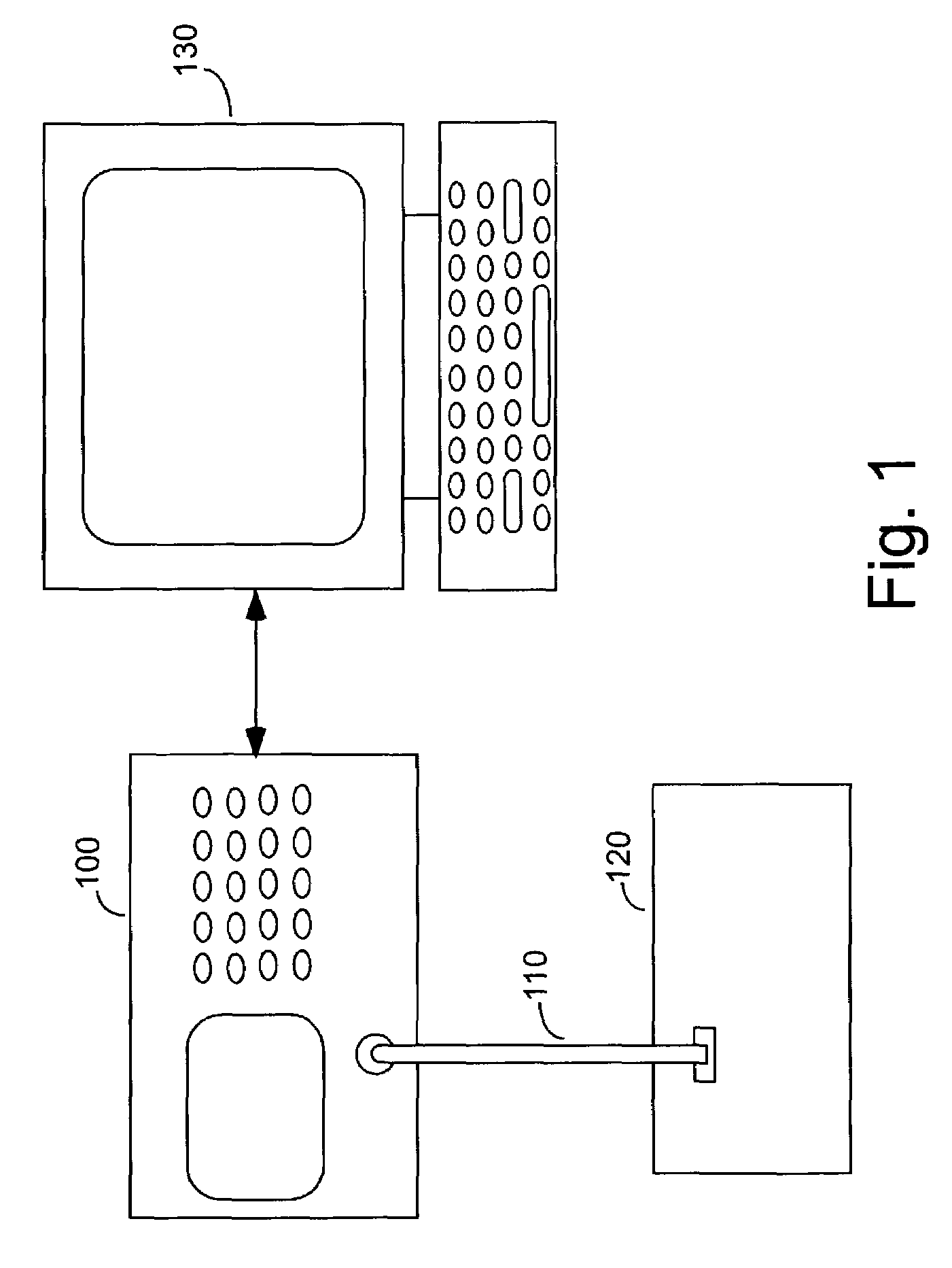
[0017]Referring to FIG. 1, a logic analyzer 100 is coupled to a system under test 120 (also known as a “target system”, or simply “target”) by a cable and probe arrangement 110 for receiving binary signals corresponding to transactions appearing on the bus of the target system. One skilled in the art will quickly realize that cable and probe arrangement 110 is shown in a highly simplified manner, and in reality, may encompass a multitude of cables and probes coupled to hundreds of test points. Logic analyzer 100 may also be coupled to, and communicate with, a computer system 130, or may operate in a stand-alone mode.

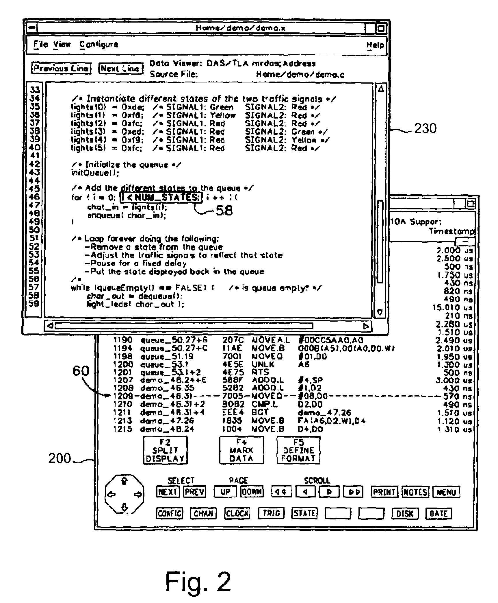
[0018]Referring to FIG. 2, a screen display 200 of logic analyzer 100 is overlaid by a screen display 230 of computer 130. Individual portions of these screen displays are highlighted to show a correspondence of a line of assembly code 60 of a program running on target system 120 with a particular line of high-level source code 58 of that same program. It is important to...


PUM


Abstract

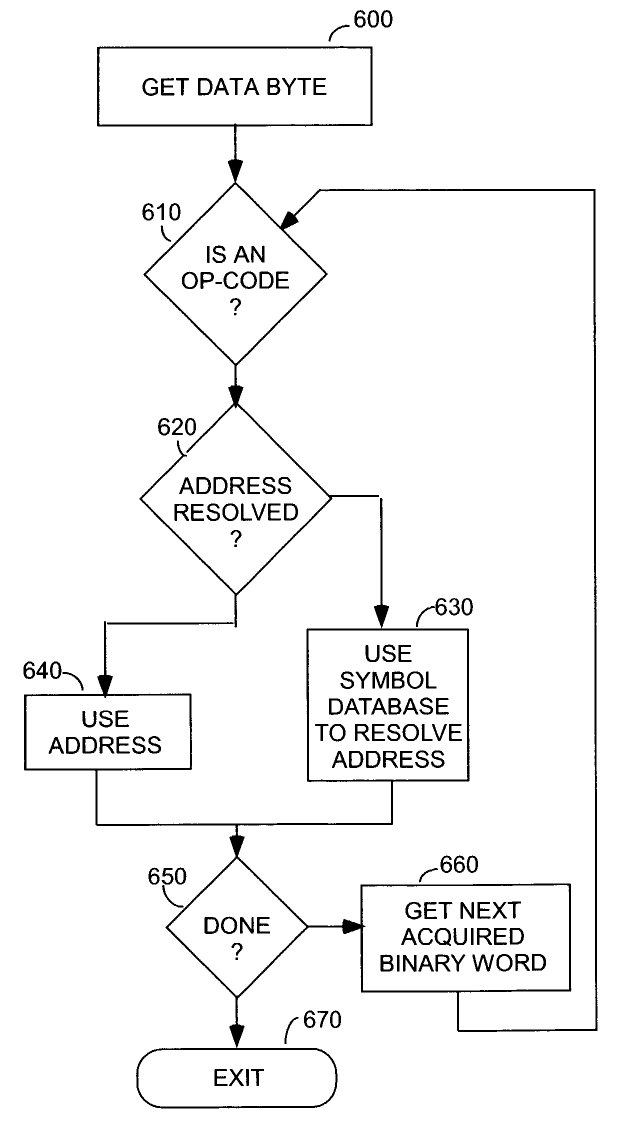
A logic analyzer according to the subject invention includes a disassembler for disassembling object code. The disassembler automates the process of locating op-code addresses by utilizing information derived from an object file corresponding to the code whose execution is being disassembled. The object file includes addresses for the starting location of op-codes corresponding to individual source code lines. When the disassembler cannot determine the correct starting location for an op-code, it uses information from the object file to obtain the address of an op-code within a specified range of interest.

Description

CLAIM FOR PRIORITY[0001]The subject application claims priority from U.S. Provisional Patent Application Ser. No. 60 / 326,548 METHOD FOR USING SYMBOL TABLE INFORMATION TO IDENTIFY OP-CODES DURING DISASSEMBLY (David L. Bennett, et al.) filed 01 Oct. 2001.FIELD OF THE INVENTION[0002]This invention relates to test and measurement systems and, more particularly, to a disassembler for use in a logic analyzer for more precisely determining the starting address of assembly language code statements running on a system under test.BACKGROUND OF THE INVENTION[0003]In earlier days, engineers typically wrote control code for test and measurement systems in assembly language, a low-level language. Today, however, to improve development time and to enable the creation of programs having greater functionality and complexity to be developed in shorter time, engineers typically employ high-level languages, for example C, C++, etc. The high-level language is converted into machine code for operation on...

Claims


Application Information

Patent Timeline
Patent Type & Authority Patents(United States)
IPC IPC(8): G06F11/00G06F11/36H04L1/22
CPCG06F8/53G06F11/3624
Inventor BENNETT, DAVID L.HEATH, ROBERT J.MILLARD, MARK L.
Owner TEKTRONIX INC
Learn More