
Cleaning tool with rotatably driven working tool

Inactive Publication Date: 2007-07-24
DUPRO AG
View PDF3 Cites 2 Cited by
  • Summary
  • Abstract
  • Description
  • Claims
  • Application Information

AI Technical Summary

Benefits of technology

[0006]It is an object of the present invention to configure the cleaning tool having a rotatably driven working tool such that an easy exchange of the working tool is possible without any impairment of the changing action as a result of the drive.
[0011]The V-gear acting in the gap between the driving wheel and the driven wheel must not be positionally secured for achieving a force-transmitting connection. The V-gear and / or one of the gear wheels can be movable relative to one another. When the V-gear rotates about an axis of rotation secured on the housing, a radial bearing clearance of at least one wheel or of the V-gear is expedient. The bearing clearance ensures a relative movement of the V-gear to the driving wheel and the driven wheel so that a torque transmitting engagement of the gear connection is ensured. Advantageously, the rotary center points of the driving wheel and of the driven wheel are fixed at the housing and the V-gear is movable in the gap between the wheels. In this way, the V-gear can be secured on a pivot arm that is fixedly connected to the housing and forces the V-gear with a contacting force into the V-grooves of the pulleys. The contacting force can be a weight force and / or a spring force. Advantageously, a stop limits the insertion movement of the V-gear into the gap between the wheels and, in this way, lowers stress of the gear system.

Problems solved by technology

The belt is usually guided about the base member of the brush roller so that it is difficult to exchange the brush roller.

Method used


Image

  • Cleaning tool with rotatably driven working tool
  • Cleaning tool with rotatably driven working tool
  • Cleaning tool with rotatably driven working tool

Examples


Embodiment Construction

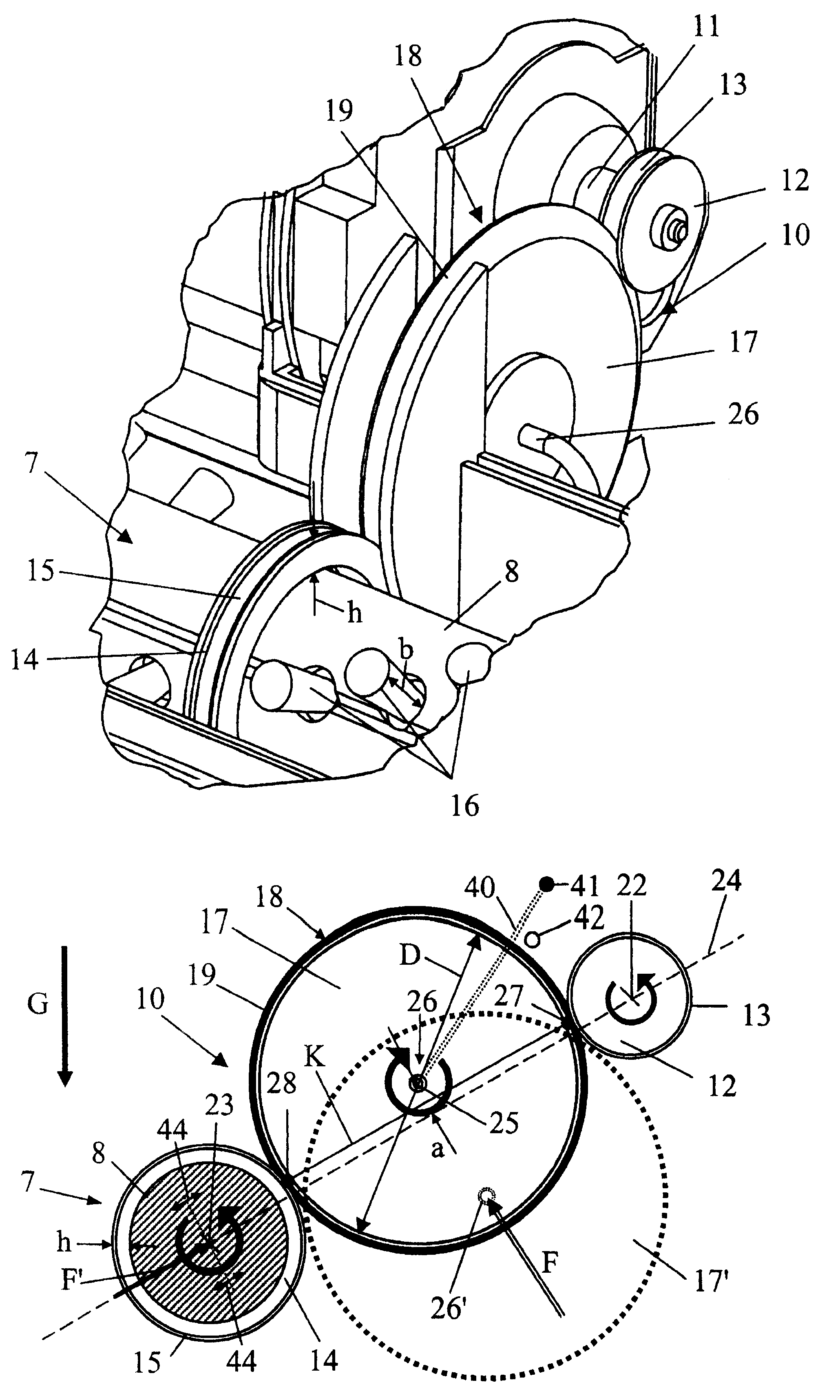
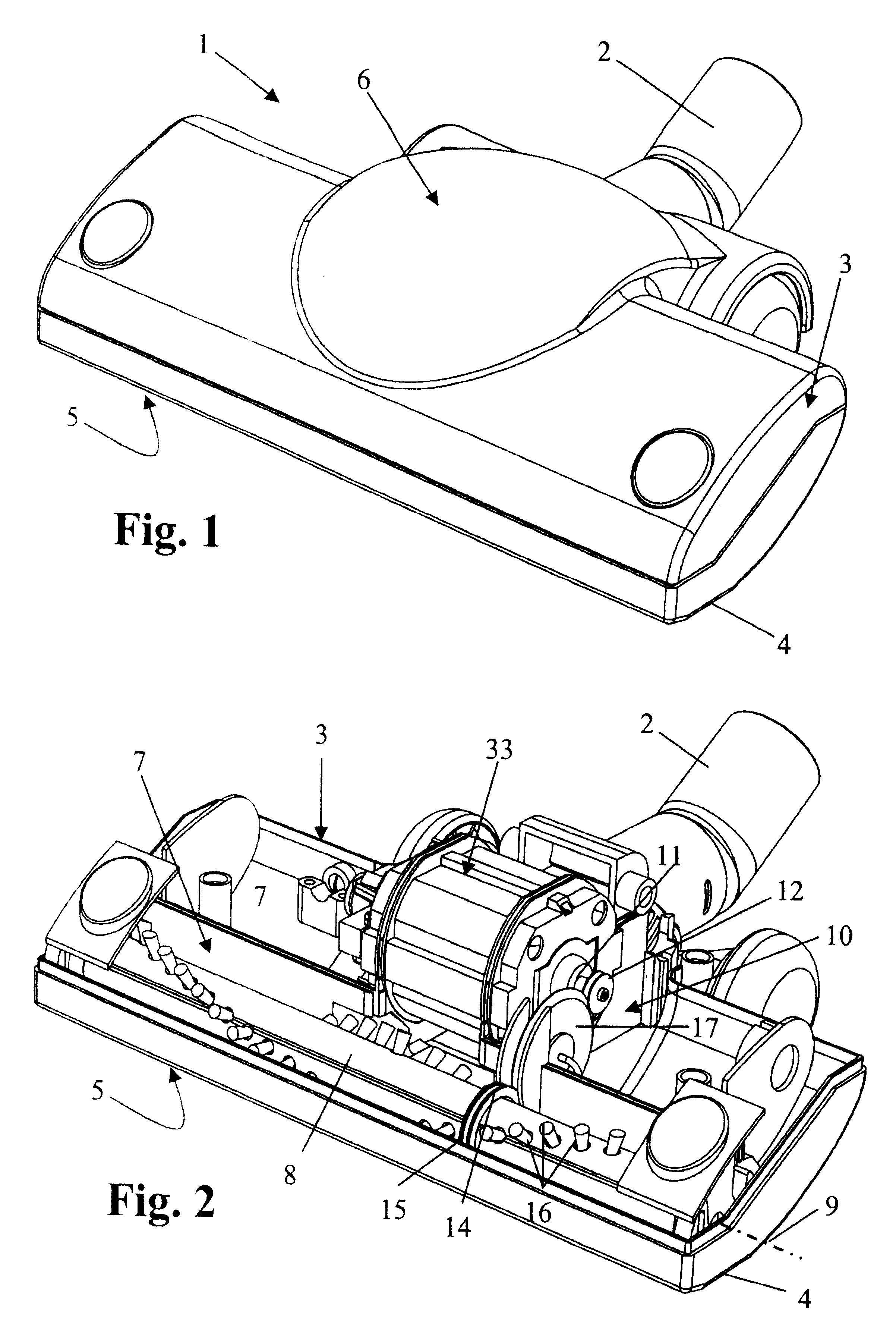
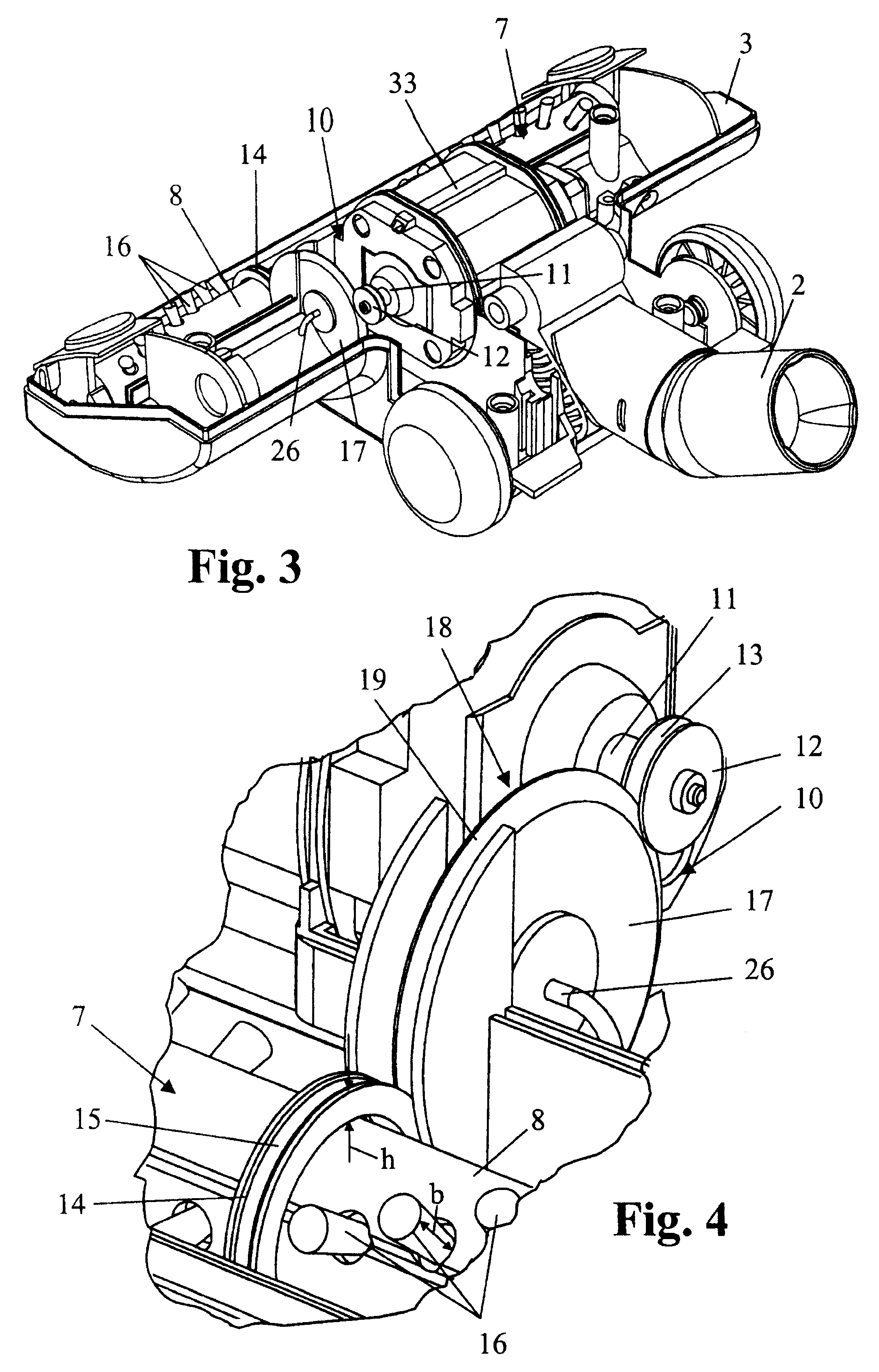
[0022]The cleaning tool 1 schematically illustrated in FIG. 1 is a vacuum cleaning tool that is connected in particular to a vacuum cleaning device (not illustrated) such as a vacuum cleaner or the like via a vacuum socket 2. In the illustrated embodiment, the cleaning tool 1 is comprised of a two-part housing 3 having a bottom plate 4 in which a working slot 5 is provided. In the housing 3, a drive unit 6 is integrated; in the illustrated embodiment, it comprises an electric motor 33 that can be seen in FIG. 2 because the upper housing part is removed. In the illustrated embodiment, the working tool 7 is a brush roller supported in the housing 3 so as to rotate about a horizontal axis 9 and acting through the working slot 5 provided in the bottom plate 4 onto the surface to be cleaned or treated, for example, a floor.

[0023]The drive motor that is supported in the housing 3 and is embodied as an electric motor or also as an air turbine, e.g., a Pelton turbine, flow-through turbine o...


PUM


Abstract

A cleaning tool for a vacuum cleaning device has a housing having a bottom plate with a working slot. A rotatingly driven working tool is rotatably supported in the housing and passes through the working slot to act on a surface to be cleaned. A motor is arranged in the housing and has a motor shaft. A gear system is connected between the motor and the working tool, wherein the gear system has a driving wheel driven by the motor shaft and a driven wheel fixedly connected to the working tool. The driving wheel and the driven wheel are V-belt pulleys and have a peripheral groove, respectively. The gear system further has a V-gear positioned between the driving wheel and the driven wheel, wherein the V-gear has an outer periphery that engages the peripheral grooves for establishing a driving connection between the driving wheel and the driven wheel.

Description

BACKGROUND OF INVENTION[0001]1. Field of the Invention[0002]The invention relates to a cleaning tool having a rotatably driven working tool, in particular, for use in connection with a vacuum cleaning device such as a vacuum cleaner or the like. The cleaning tool comprises a housing with a bottom plate, and the bottom plate has a working slot through which the working tool that is rotatably supported in the housing acts on a surface to be worked on. A motor is arranged in the housing and drives by means of a gear system the working tool. The gear system comprises a driving wheel driven by the motor shaft as well as a driven wheel fixedly connected to the working tool.[0003]2. Description of the Related Art[0004]Cleaning tools configured as a vacuum cleaning tool with a rotatingly driven brush roller are known as attachments for vacuum cleaners. The vacuum cleaning tool is comprised of a housing with a bottom plate having a working slot extending transversely to the working direction...

Claims


Application Information

Patent Timeline
IPC IPC(8): A47L9/04A47L5/26F16H13/02
CPCA47L9/0411A47L9/0444A47L9/045F16H13/02
Inventor WORWAG, PETER
Owner DUPRO AG
Learn More