

Molecularly self-assembling nanocomposite barrier coating for gas barrier application and flame retardancy
- Summary
- Abstract
- Description
- Claims
- Application Information
AI Technical Summary
Benefits of technology
Problems solved by technology
Method used
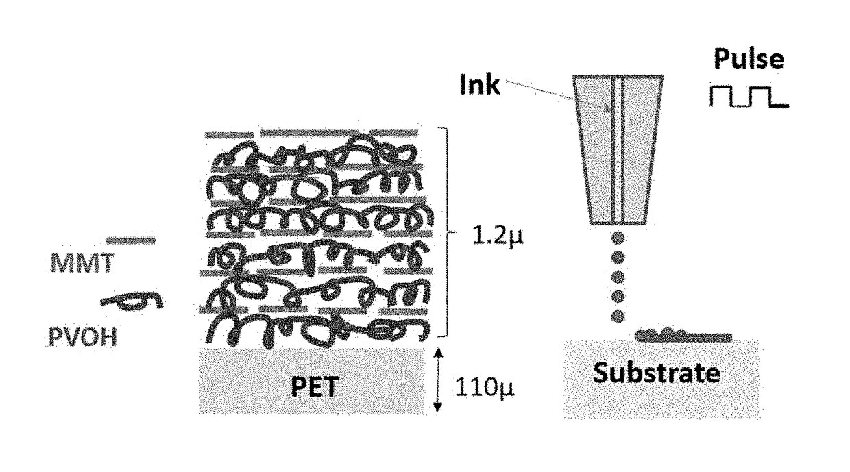
Image

Examples
example 1
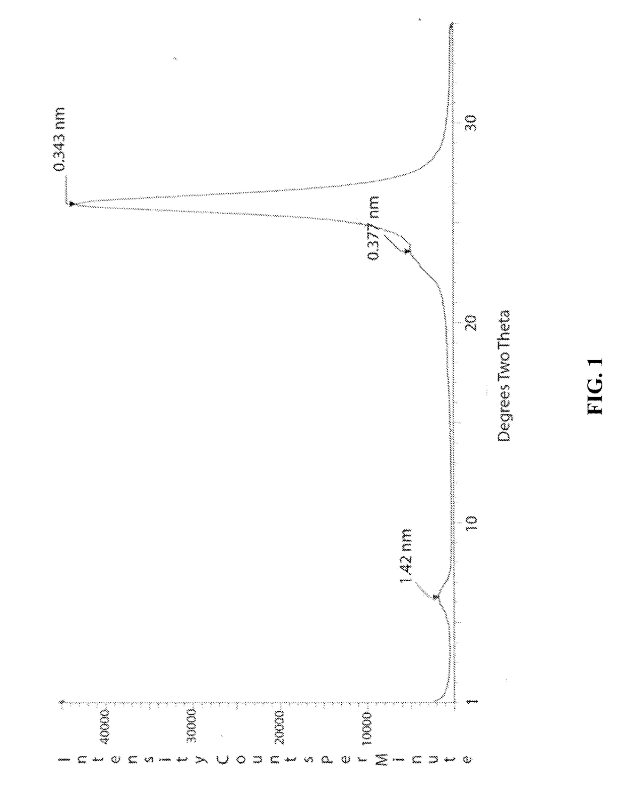
[0077]In this example a solution of polyvinylalcohol (PVOH) was made at 0.2% by weight. Likewise, dilute solutions of sodium montmorillonite were made at 0.2% by weight. These solutions were printed sequentially with an ink jet printer onto a MYLAR substrate in 2.5 cm squares. A total of 6 squares were printed with the first having one bilayer and the second having two bilayers continuing up to the sixth square that had six bilayers. The squares were then x-rayed in a powder diffractometer. FIG. 1 shows the x-ray powder pattern of the sample containing 6 bilayers. The large diffraction peak at about 25 degrees two theta is from the PET substrate as well as the smaller peak at about 23.6 degrees. The only peak arising from the coating is a broad weak peak at 6.28 degrees. This peak is characteristic of hydrated montmorillonite.
example 2
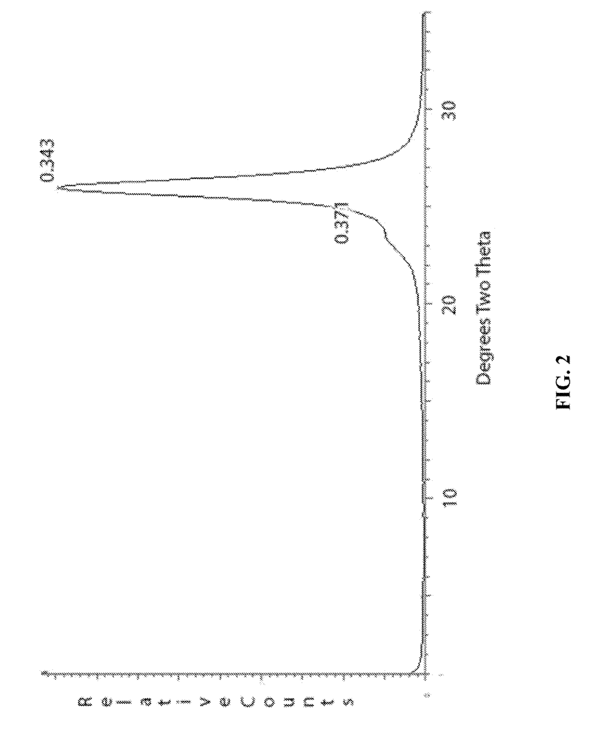
[0078]In this example a solution of polyethylene oxide (PEO) was made at 0.2% by weight. Likewise, dilute solutions of sodium montmorillonite were made at 0.2% by weight. These solutions were printed sequentially with an ink jet printer onto a MYLAR substrate in 2.5 cm squares. A total of 6 squares were printed with the first having one bilayer and the second having two bilayers continuing up to the sixth square that had six bilayers. The squares were then x-rayed in a powder diffractometer. FIG. 2 shows the x-ray powder pattern of the sample containing 6 bilayers. The large diffraction peak at about 25 degrees two theta is from the PET substrate as well as the smaller peak at about 23.6 degrees. The only peak arising from the coating is a broad weak peak at around 4 degrees that is barely discernable. This peak is characteristic of montmorillonite intercalated with one layer of PEO.
example 3
[0079]In this example a solution of polyvinylpyrrolidone (PVP) was made at 0.2% by weight. Likewise, dilute solutions of sodium montmorillonite were made at 0.2% by weight. These solutions were printed sequentially with an ink jet pl inter onto a MYLAR substrate in 2.5 cm squares. A total of 6 squares were printed with the first having one bilayer and the second having two bilayers continuing up to the sixth square that had six bilayers. The squares were then x-rayed in a powder diffractometer. FIG. 3 shows the x-ray powder pattern of the sample containing 3 bilayers. It can be seen that the peaks for the PET substrate are still present however they are much diminished compared to the previous examples. In addition, there are a series of very sharp intense peaks starting at 1.59 degrees two theta arising from an intercalated complex formed between the PVP and the clay. The first peak represents a d-spacing of approximately 55 angstroms and the other peaks at higher angle or orders o...
PUM
| Property | Measurement | Unit |
|---|---|---|
| Weight | aaaaa | aaaaa |
| Composition | aaaaa | aaaaa |
| Transparency | aaaaa | aaaaa |
Abstract
Description
Claims
Application Information