


Quick Research
Generate reliable direction feasibility study reports for your R&D in just a few steps.

Technical Q&A
Discover and master advanced knowledge NOW. Basics, ideas, possibilities, all at once.

Find Solutions
As an expert in R&D theories, this can generate solutions to your technical problems instantly.

Evaluate Feasibility
Analyze your overall solution with one click, know your potential R&D risks in advance.

Monitor Landscape
Get weekly tech updates, stay abreast of the latest tech innovations and key insights.
Method for the recognition of the synchronization position and the end of the synchronization operation of an automated shiftable transmission
a technology of automatic shiftable transmission and synchronization position, which is applied in the direction of mechanical actuators, mechanical actuating clutches, transportation and packaging, etc., can solve the problems of increasing the load current of the actuator, the middle synchronization position is moved, and the detection of the load current is comparatively complicated and expensiv
- Summary
- Abstract
- Description
- Claims
- Application Information
AI Technical Summary
Benefits of technology
Problems solved by technology
Method used
Image

Examples
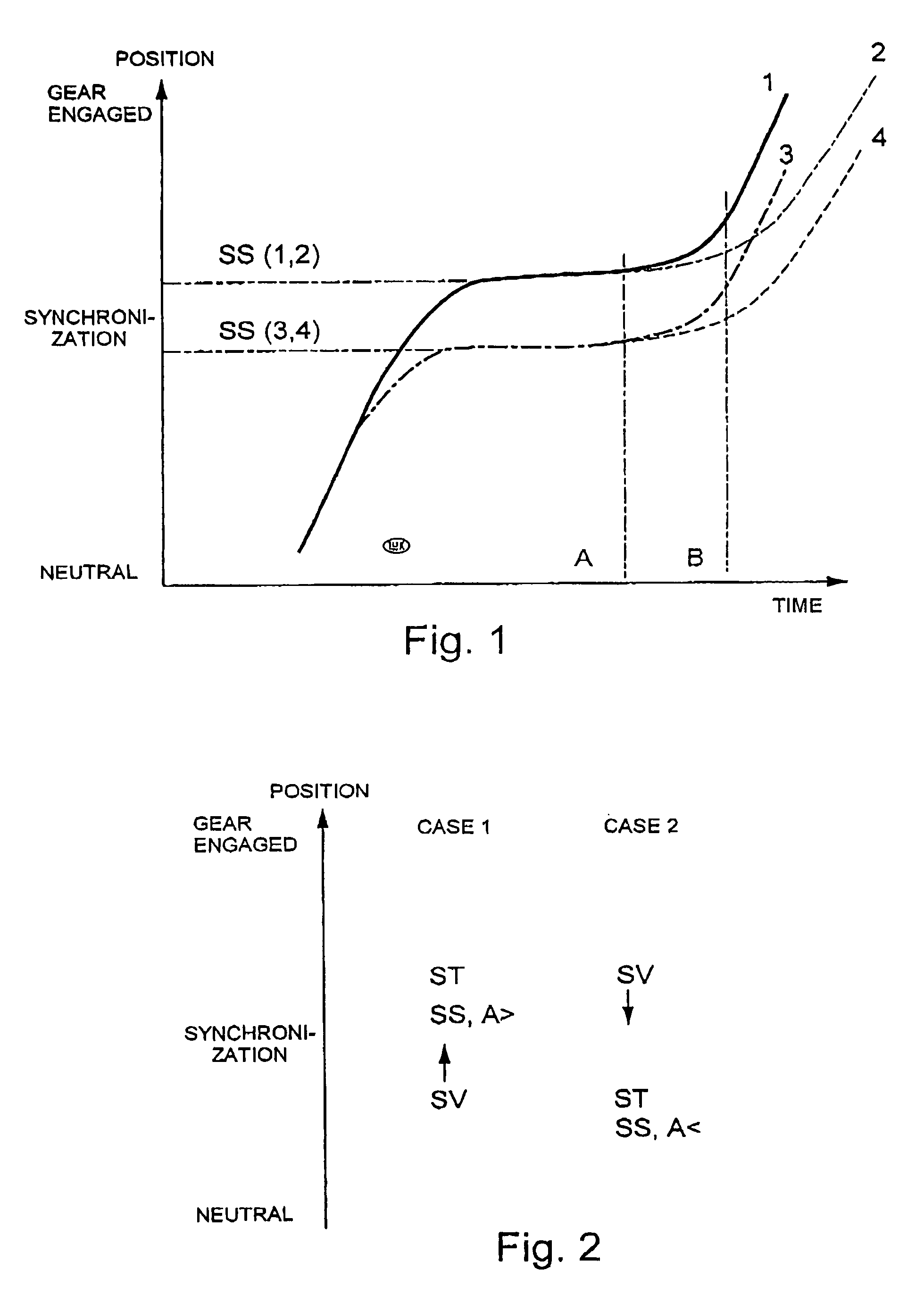
case 2
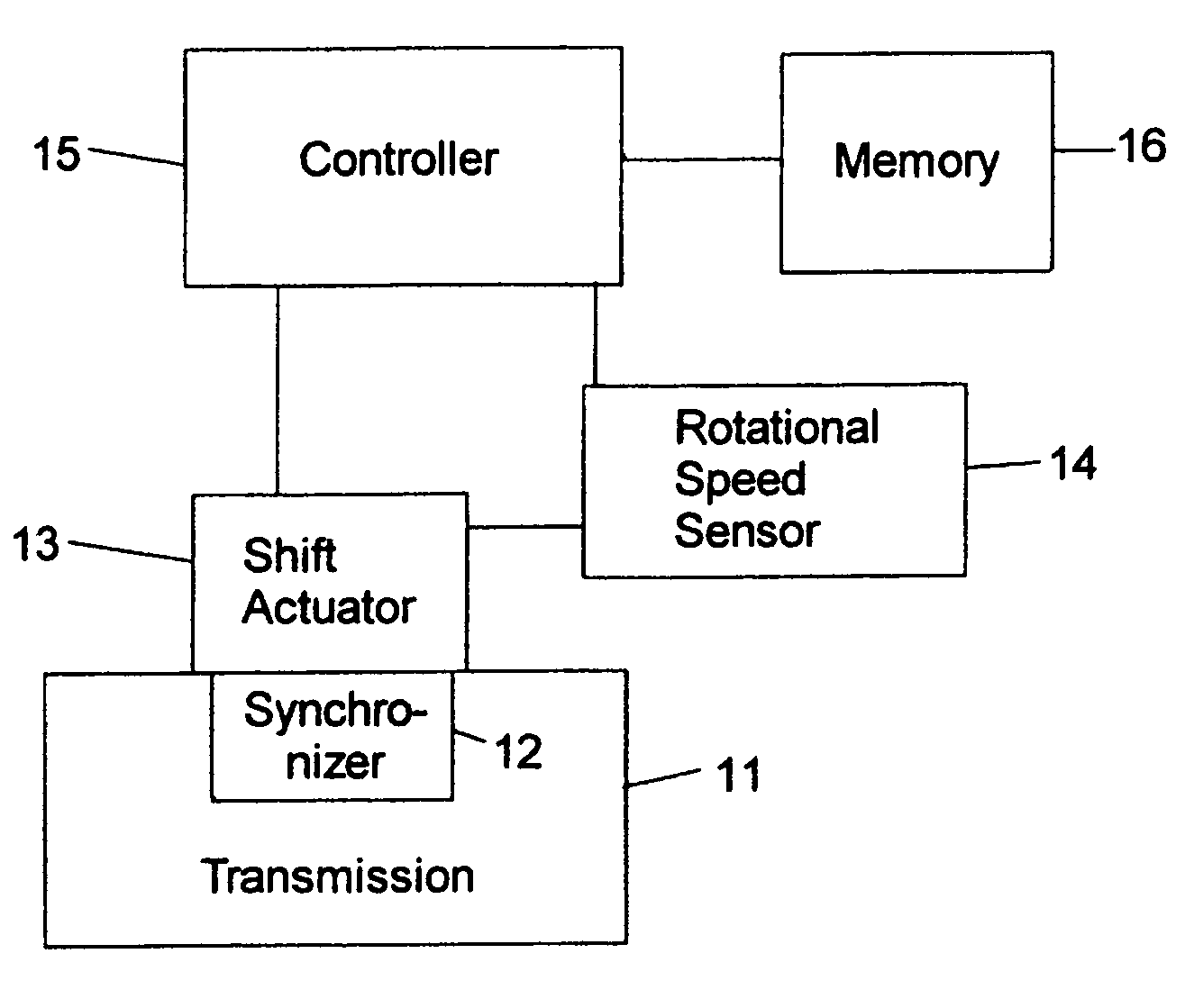
[0040 shows that the actual synchronization position (ST) lies closer to the neutral position than the assumed (stored) synchronization position (SV). A low acceleration (A13 has had to work against the blocking effect of the synchronizing means 12 during the synchronization operation. An adaptation of the assumed (stored) synchronization position (SV) in the direction closer to the neutral position is thus appropriate.
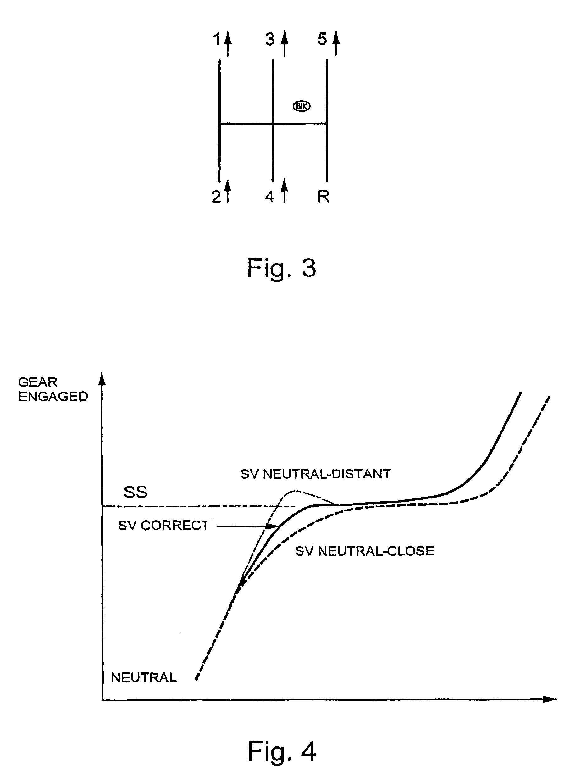
[0041]FIG. 3 shows an illustration to explain a unidirectional displacement of the entire shift pattern. In relation to the neutral position, a change (displacement) of the synchronization position for each forward gear has occurred in the same direction, which direction change is shown by the upwardly directed arrows. Therefore, it can be concluded that the entire shift pattern has moved altogether and an adaptation of the assumed synchronization position (SV) by the controller 15 is thus not necessary.
[0042]Lastly, FIG. 4 serves to explain the importance of the sync...
PUM
 Abstract
Description
Claims
Application Information
 - R&D Engineer
- R&D Manager
- IP Professional
- Industry Leading Data Capabilities
- Powerful AI technology
- Patent DNA Extraction
Browse by: Latest US Patents, China's latest patents, Technical Efficacy Thesaurus, Application Domain, Technology Topic, Popular Technical Reports.
© 2024 PatSnap. All rights reserved.Legal|Privacy policy|Modern Slavery Act Transparency Statement|Sitemap|About US| Contact US: help@patsnap.com