Motion transmitting structure for a nozzle arrangement of a printhead chip for an inkjet printhead

a technology of inkjet printhead and nozzle arrangement, which is applied in the field of motion transmitting structure of inkjet printhead, can solve the problems of difficult and expensive fabrication of components having relatively complex shapes, inability to achieve a working configuration, and constraints on the form of fabrication

Inactive Publication Date: 2007-07-24
SILVERBROOK RES PTY LTD +1
View PDF78 Cites 29 Cited by
  • Summary
  • Abstract
  • Description
  • Claims
  • Application Information

AI Technical Summary

Benefits of technology

[0002]This invention relates to a printhead chip. More particularly, this invention relates to a printhead chip that incorporates a plurality of nozzle arrangements that each include a motion transmitting structure.

Problems solved by technology

As set out in the above referenced applications / patents, the Applicant has spent a substantial amount of time and effort in developing printheads that incorporate micro electro-mechanical system (MEMS)—based components to achieve the ejection of ink necessary for printing.
A particular difficulty that the Applicant has been faced with is to achieve a suitable interface between a prime mover in the form of an actuator and the moving component.
Such forms of fabrication are subject to constraints since they involve successive deposition and etching techniques.
It follows that MEMS-based devices are usually formed in layers and that components having relatively complex shapes are difficult and expensive to fabricate.
However, the Applicant has found that it is not possible to achieve a working configuration as shown by using MEMS-based fabrication techniques.
In particular, it has been found by the Applicant that such a unitary structure does not lend itself to such fabrication techniques.

Method used


Image

  • Motion transmitting structure for a nozzle arrangement of a printhead chip for an inkjet printhead
  • Motion transmitting structure for a nozzle arrangement of a printhead chip for an inkjet printhead
  • Motion transmitting structure for a nozzle arrangement of a printhead chip for an inkjet printhead

Examples


Embodiment Construction

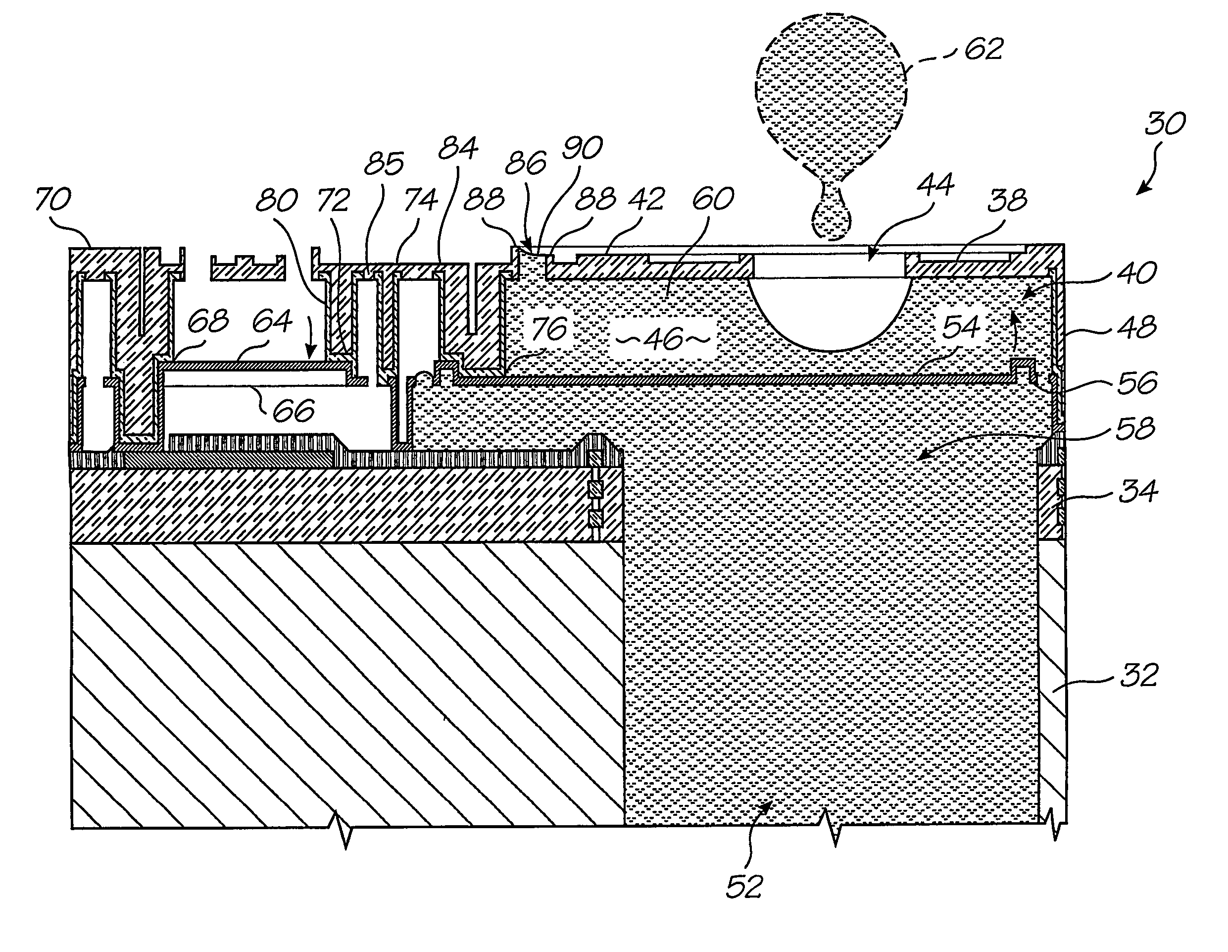
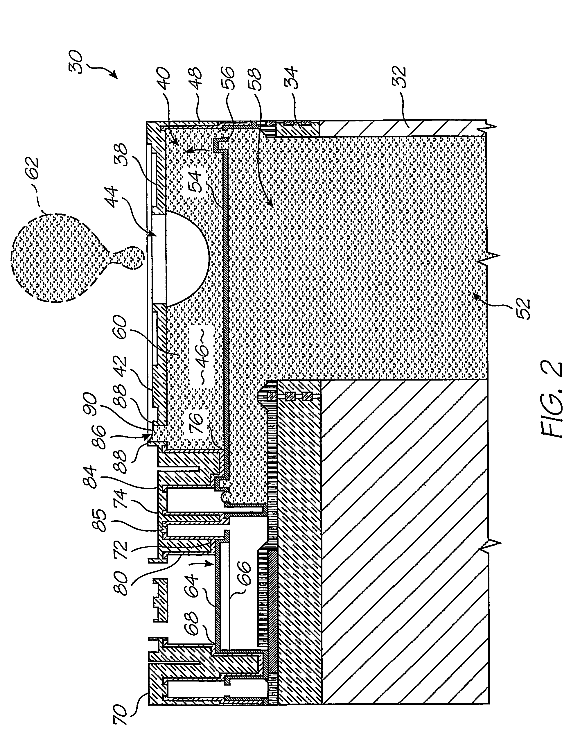
[0025]In FIG. 2, reference numeral 30 generally indicates a nozzle arrangement of a first embodiment of an ink jet printhead chip, in accordance with the invention, for an inkjet printhead.

[0026]The nozzle arrangement 30 is one of a plurality of such nozzle arrangements formed on a silicon wafer substrate 32 to define the printhead chip of the invention. As set out in the background of this specification, a single printhead can contain up to 84 000 such nozzle arrangements. For the purposes of clarity and ease of description, only one nozzle arrangement is described. It is to be appreciated that a person of ordinary skill in the field can readily obtain the printhead chip by simply replicating the nozzle arrangement 30 on the wafer substrate 32.

[0027]The printhead chip is the product of an integrated circuit fabrication technique. In particular, each nozzle arrangement 30 is the product of a MEMS—based fabrication technique. As is known, such a fabrication technique involves the dep...


PUM


Abstract

A printhead chip for an inkjet printhead includes a plurality of nozzle arrangements (100) positioned on a substrate (32). Each nozzle arrangement includes a chamber structure defining a nozzle chamber (106) that receives ink. An ink ejecting member (140) positioned in the nozzle chamber is displaceable in the nozzle chamber to eject ink from the nozzle chamber. Each nozzle actuator (148) is positioned on the substrate, the actuator having a working portion (156) displaceable with respect to the substrate when the actuator receives a driving signal. A sealing structure (130) is positioned on the substrate between the actuator and the ink-ejecting member inhibiting ink flow between the ink ejecting member and the actuator. A motion transmitting structure (122) pivotally bridges the sealing structure and interconnects the working portion (156) of the actuator and the ink-ejecting member (140) to transmit displacement of the working portion relative to the substrate to the ink ejecting member. Slotted openings (174) form a pair of opposed flexural connectors (178) between the outer structure (170) and the motion transmitting structures (122) allowing torsional deformation accommodating pivotal movement during operation of the nozzle arrangement.

Description

[0001]The present application is a 371 of PCT / AU02 / 00762 filed on Jun. 13, 2002, which is a continuation of U.S. application Ser. No. 10 / 120,347 filed on Apr. 12, 2002, now issued U.S. Pat. No. 6,540,332, which is a continuation in part of U.S. application Ser. No. 09 / 112,767 filed on Jul. 10, 1998, now issued U.S. Pat. No. 6,416,167.FIELD OF THE INVENTION[0002]This invention relates to a printhead chip. More particularly, this invention relates to a printhead chip that incorporates a plurality of nozzle arrangements that each include a motion transmitting structure.BACKGROUND OF THE INVENTION[0003]As set out in the above referenced applications / patents, the Applicant has spent a substantial amount of time and effort in developing printheads that incorporate micro electro-mechanical system (MEMS)—based components to achieve the ejection of ink necessary for printing.[0004]As a result of the Applicant's research and development, the Applicant has been able to develop printheads havin...

Claims


Application Information

Patent Timeline
Patent Type & Authority Patents(United States)
IPC IPC(8): B41J2/04B41J2/05B41J2/14B41J2/155B41J2/16B41J2/165B41J2/175B41J3/42B41J3/44B41J11/70B41J15/04B81B3/00H04N1/21H04N5/225H04N5/262
CPCB41J2/14427B41J2/1601B41J2/1623B41J2/1626B41J2/1628B41J2/1629B41J2/1631B41J2/1632B41J2/1635B41J2/1637B41J2/1639B41J2/1642B41J2/1643B41J2/1645B41J2/1646B41J2/1648B41J2/17513B41J3/445B41J11/70B41J15/04H04N5/225H04N5/2628B41J2/16585B41J2/17596B41J2002/041B41J2202/21H04N23/00B41J2/14B41J2/04
Inventor SILVERBROOK, KIA
Owner SILVERBROOK RES PTY LTD
Why Eureka
Try Eureka