Acoustic sensor

a technology of acoustic sensor and acoustic sensor, which is applied in the field of acoustic sensor, can solve the problems of complex optical readout approaches which face challenging packaging and manufacturing hurdles, and the integration of multiple sensors on a single die to realize co-located pressure gradient measurements, so as to improve the signal to noise ratio of the acoustic sensor. , the effect of improving the performance of the acoustic sensor

Active Publication Date: 2014-02-27
BOARD OF RGT THE UNIV OF TEXAS SYST
View PDF8 Cites 12 Cited by
  • Summary
  • Abstract
  • Description
  • Claims
  • Application Information

AI Technical Summary

Benefits of technology

[0009]In another aspect, a plurality of detectors are employed in an acoustic sensor and a method of separating and comparing each of the detector outputs is used to improve the performance of the acoustic sensor. In some embodiments, harmonics of the plate can be removed, improving the signal to noise ratio of the acoustic sensor.

Problems solved by technology

Demonstrations to date, however, have relied on complex optical readout approaches which face challenging packaging and manufacturing hurdles.
Integration of multiple sensors on a single die to realize co-located pressure gradient measurements will also prove challenging due to alignment tolerances between optical and mechanical components.
Designing for low power consumption is yet another challenge with optical readout methodologies.

Method used


Image

  • Acoustic sensor
  • Acoustic sensor
  • Acoustic sensor

Examples


example embodiments and simulations

[0086]Network Modeling of Multiple-Port, Multiple-Vibration-Mode Transducers and Resonators

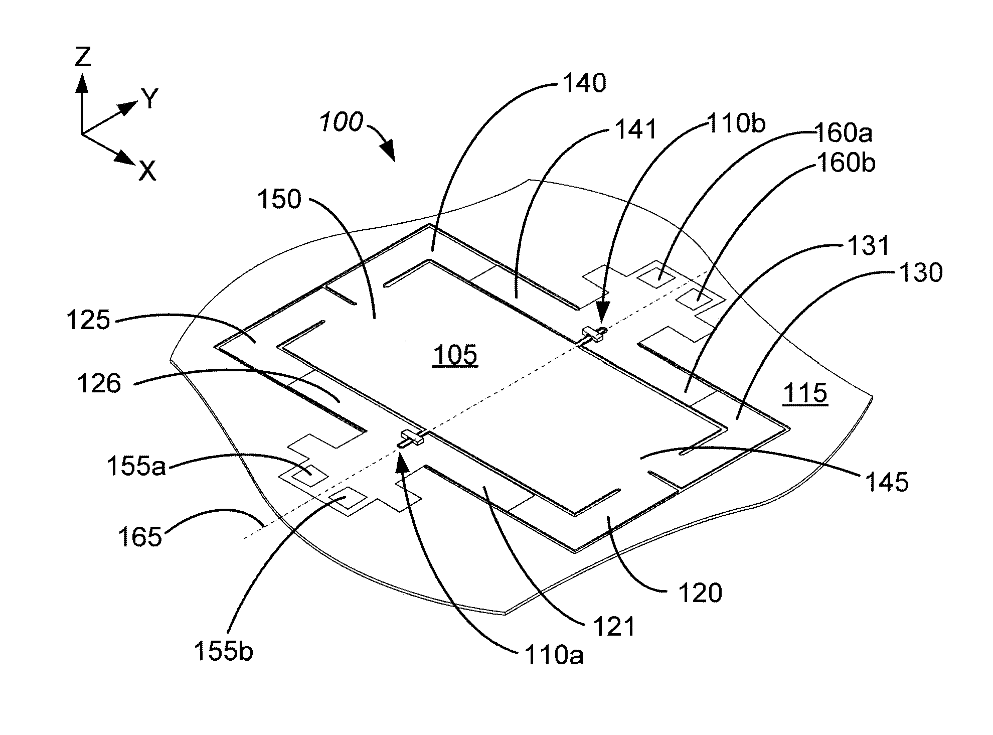
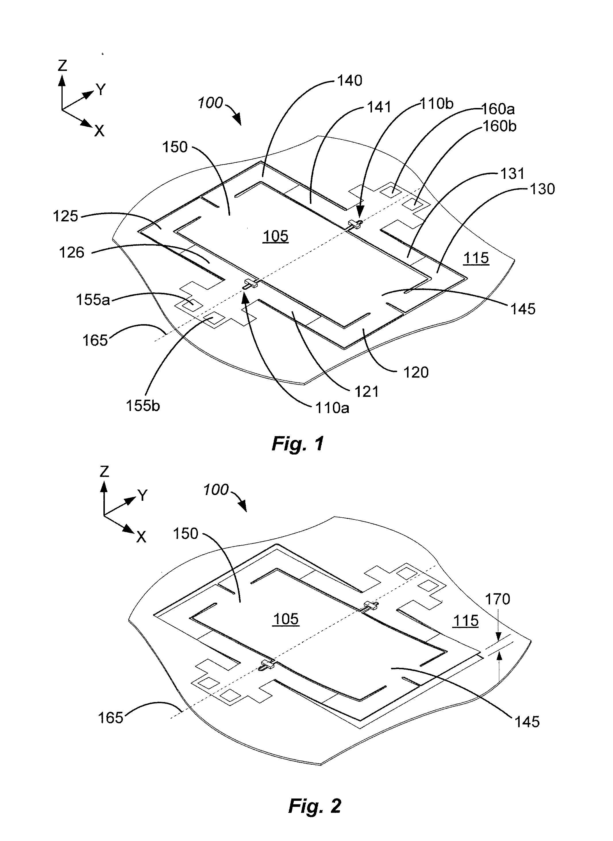
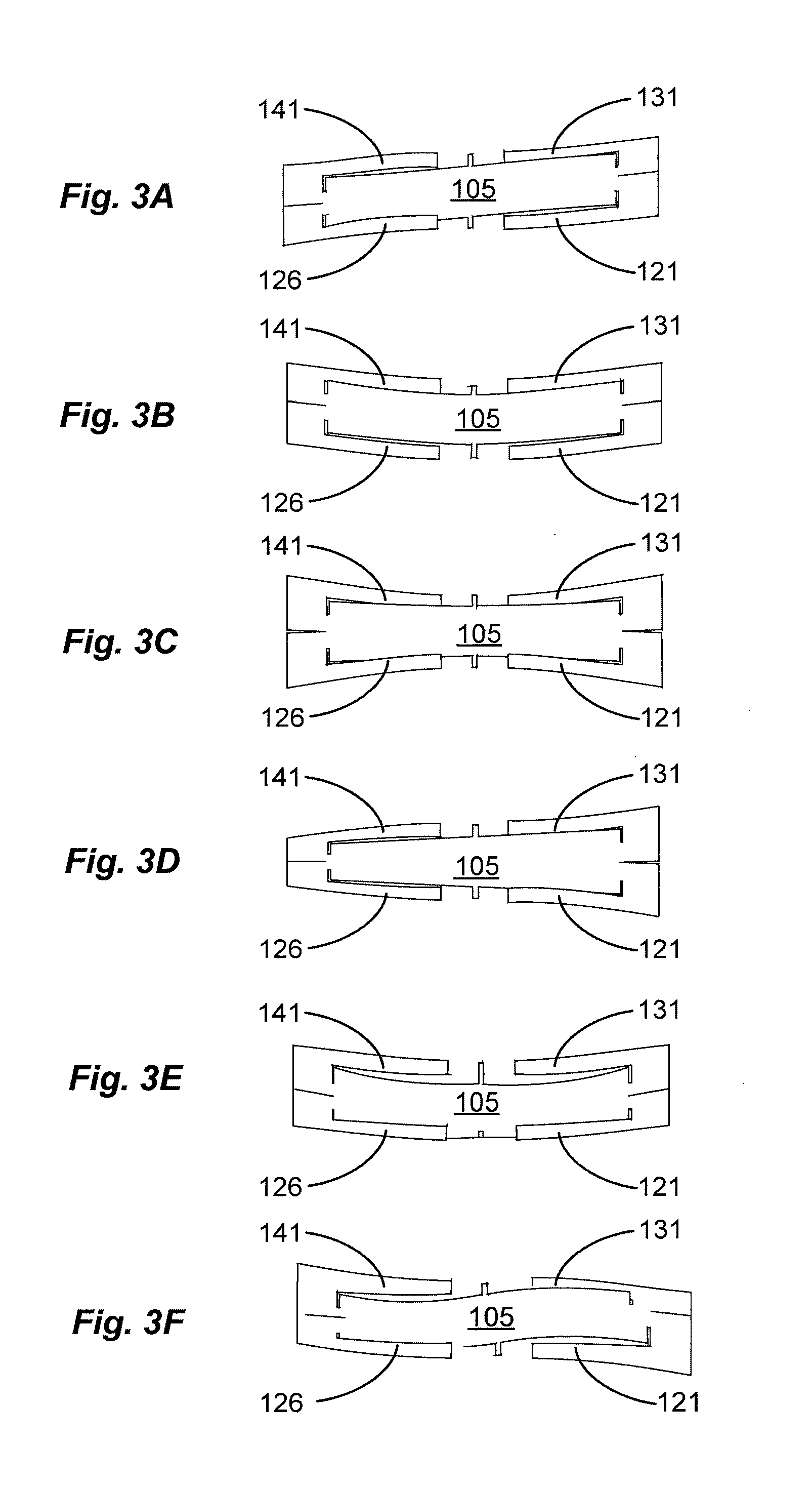
[0087]A modeling procedure is presented for multiple-port, multiple-vibration-mode transducers. Unique features of the procedure include the use of modal coordinates to describe deformations of the mechanical structure, the use of a network analog for each vibration mode of the structure, and the selection of modal velocity, rather than a particular physical velocity on the structure, as the mechanical flow variable in each modal network. Finite element analysis is used only to compute a discrete set of salient circuit parameters, with all other analysis and design computations performed using the networks. The approach is computationally efficient and assists with providing insights into the design of actuators and micromechanical resonators, where the generation and suppression of particular vibration modes may be important. A micromachined, multiple-port piezoelectric microphone with in-pla...


PUM


Abstract

A method of designing and manufacturing an acoustic sensor having a high degree of directivity is disclosed. The sensor includes a rotatable plate that is attached to a substrate with mounts. In one aspect the mounts are freely rotatable and the torque on the plate is measured using detectors disposed on springs that provide a resistance to rotation of the plate. In another aspect the plate is mounted to the substrate with mounts that torsionally deform during rotation of the plate. These detectors measure the torque on the plate according to the torsional deformation of the mounts. Methods of improving the signal to noise ratio of acoustic sensors having multiple detectors are also disclosed.

Description

CROSS-REFERENCES TO RELATED APPLICATIONS[0001]This application claims priority to U.S. Provisional Application No. 61 / 691,613, filed Aug. 21, 2012 titled “ACOUSTIC SENSOR” and to U.S. Provisional Application No. 61 / 693,111, filed Aug. 24, 2012 titled “ACOUSTIC SENSOR” which are hereby incorporated by reference in their entirety.BACKGROUND[0002]Sound is transmitted by pressure oscillations in air. A microphone is a pressure sensor designed to sense very small pressure oscillations across the audio frequency range (20 Hz-20 kHz). Typically, a compliant diaphragm is designed to deflect in proportion to sound pressure. The deflection is, in-turn, measured in a number of ways (capacitively, optically, or piezoelectrically) to ultimately produce an output voltage in proportion to the sound pressure. Piezoelectric materials produce a voltage when strained. When piezoelectric materials are patterned on a pressure sensitive diaphragm, the deflection of the diaphragm due to sound pressure str...

Claims


Application Information

Patent Timeline
Patent Type & Authority Applications(United States)
IPC IPC(8): G01H5/00
CPCG01H5/00G01H11/06H04R17/02H04R31/00H04R2201/003
Inventor HALL, NEAL A.KUNTZMAN, MICHAEL L.KIM, DONGHWANHEWA-KASAKARAGE, NISHSHANKA
Owner BOARD OF RGT THE UNIV OF TEXAS SYST
Why Eureka
Try Eureka