Shroud leading edge cooling

a technology of shrouds and shrouds, which is applied in the direction of engine cooling apparatus, motors, engine fuctions, etc., can solve the problems of reducing efficiency and reducing the efficiency of the overall turbine engin

Active Publication Date: 2007-07-24
PRATT & WHITNEY CANADA CORP
View PDF16 Cites 18 Cited by
  • Summary
  • Abstract
  • Description
  • Claims
  • Application Information

AI Technical Summary

Problems solved by technology

While cooling improves the overall efficiency of the turbine engine, some leakage occurs which reduces efficiency, as unnecessary overflow of cooling air is wasted and reduces overall turbine engine efficiency.

Method used


Image

  • Shroud leading edge cooling
  • Shroud leading edge cooling
  • Shroud leading edge cooling

Examples


Embodiment Construction

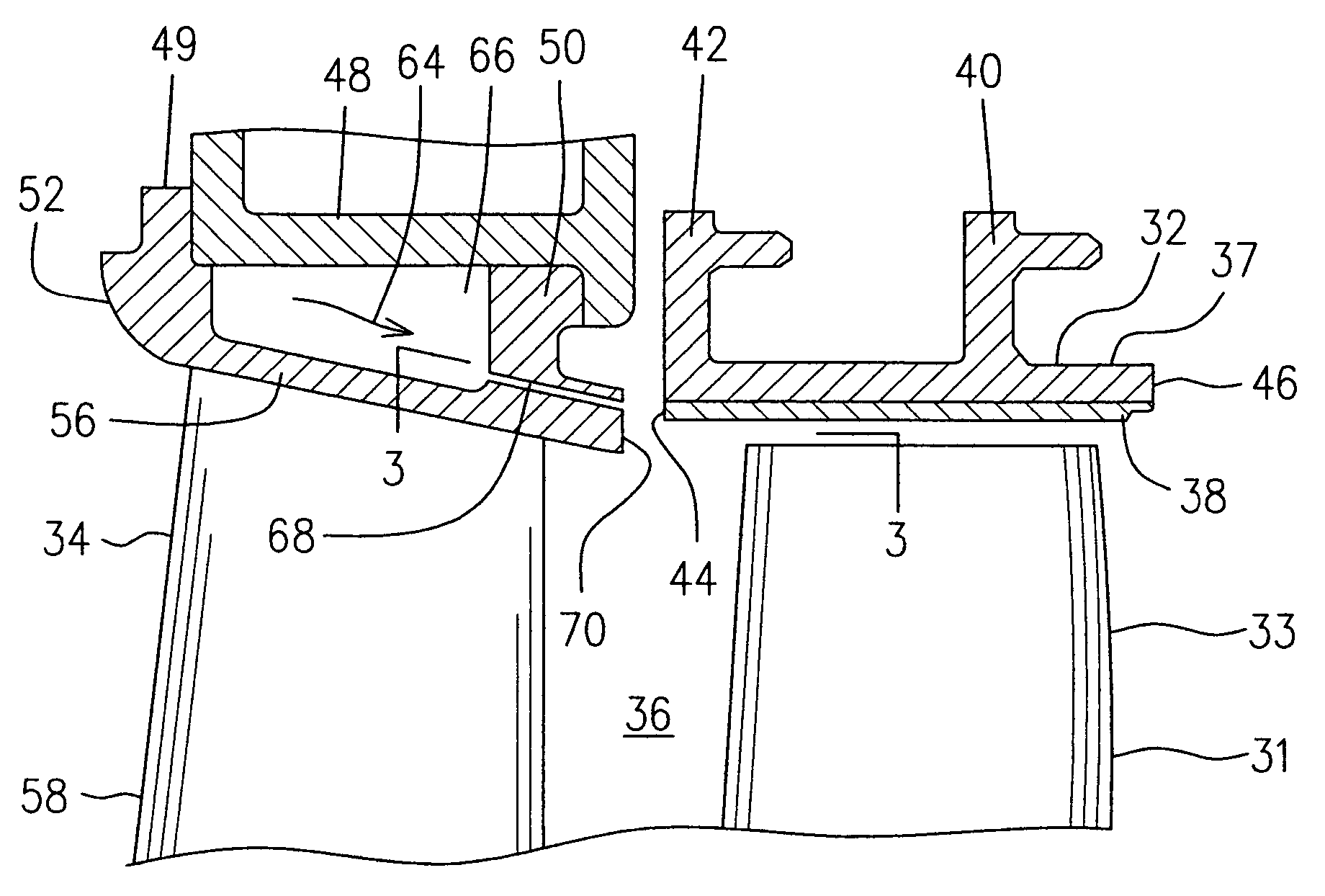
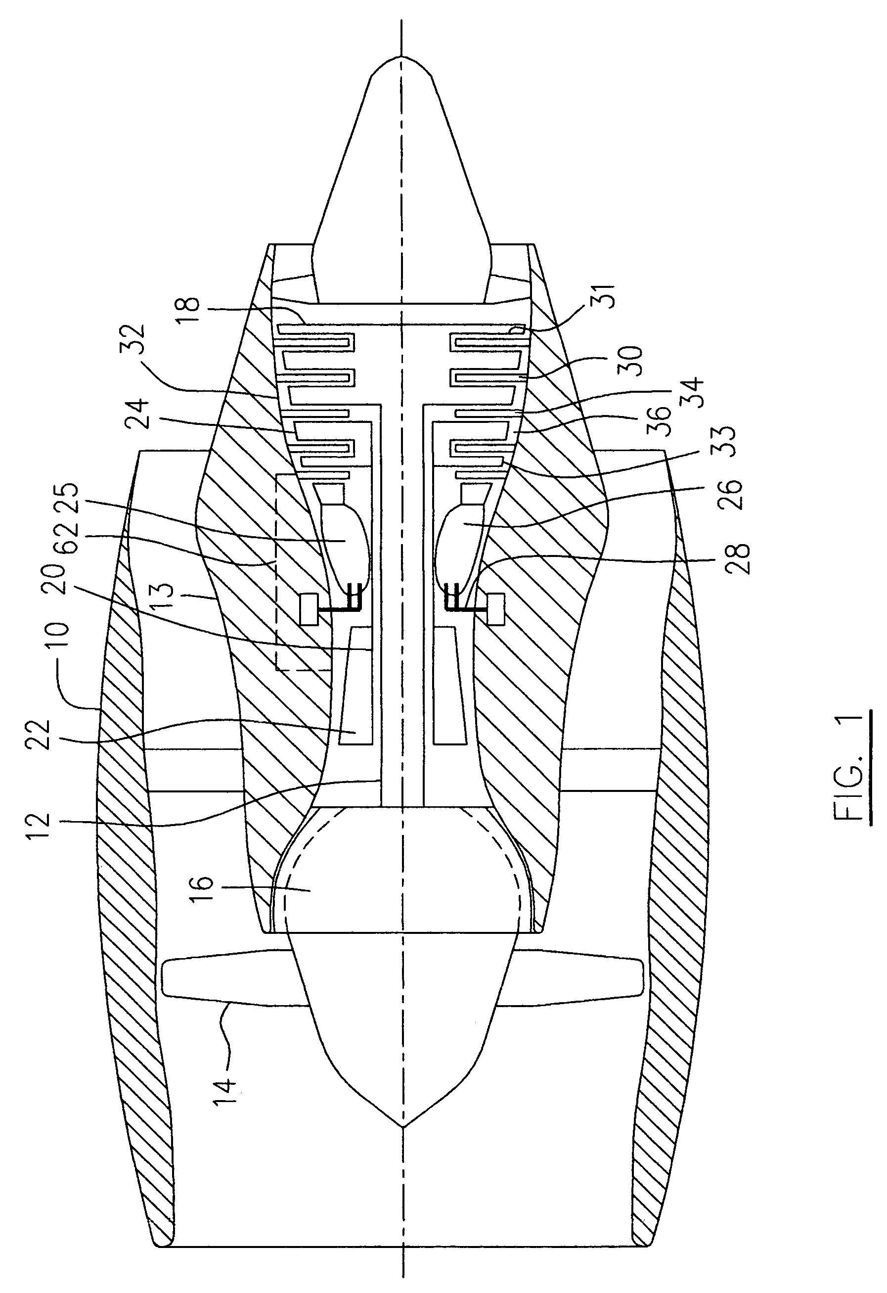
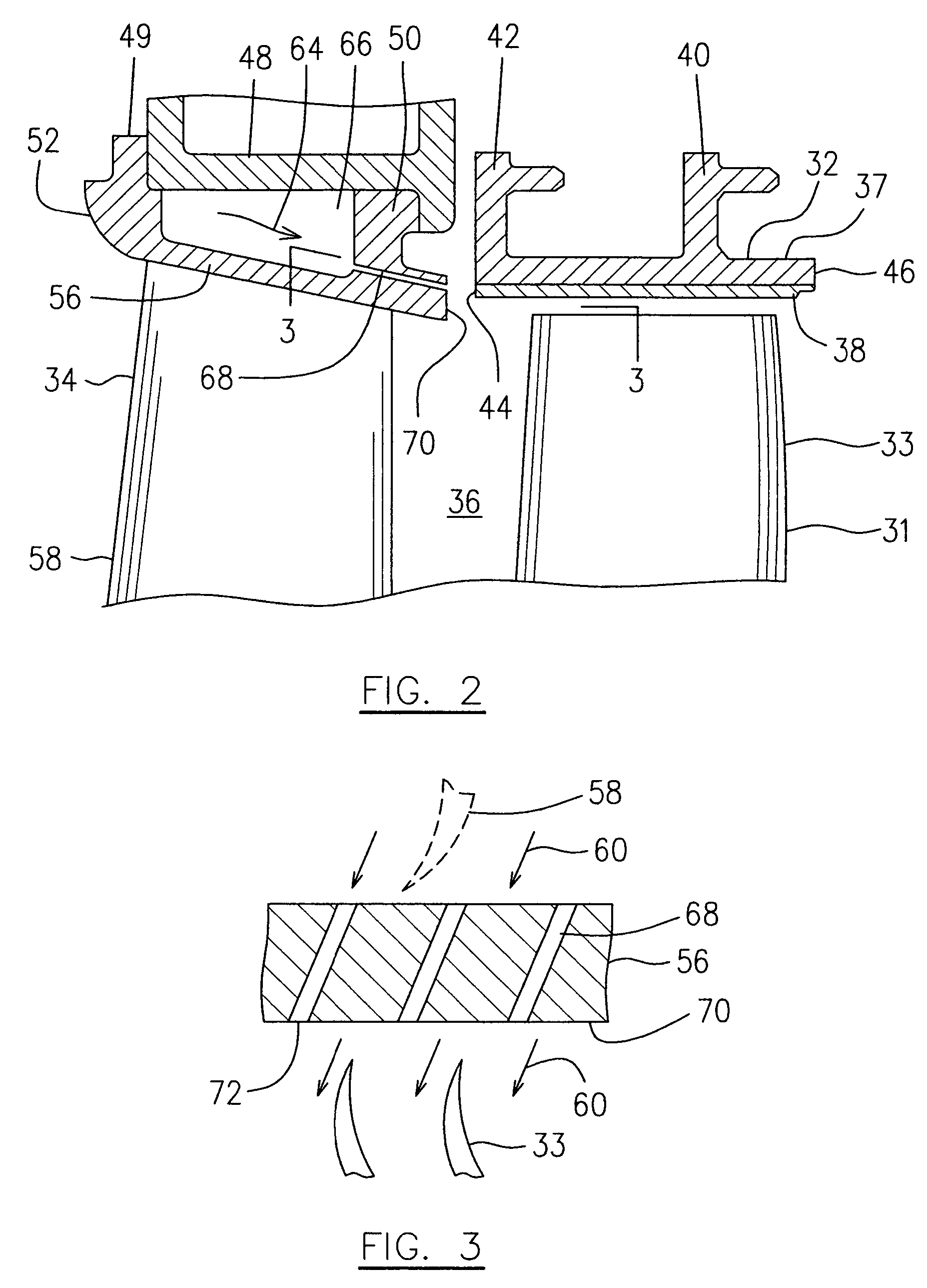
[0012]Referring to FIGS. 1 and 2, a turbofan gas turbine engine incorporating an embodiment of the present invention is presented as an example of the application of the present invention and includes a housing or a nacelle 10, a core casing 13, a low pressure spool assembly seen generally at 12 which includes a fan assembly 14, a low pressure compressor assembly 16 and a low pressure turbine assembly 18, and a high pressure spool assembly seen generally at 20 which includes a high pressure compressor assembly 22 and a high pressure turbine assembly 24. The core casing 13 surrounds the low and high pressure spool assemblies 12 and 20 to define a main fluid path (not indicated) therethrough. In the main fluid path there is provided a combustor seen generally at 25 with fuel injecting means 28, to constitute a gas generator section 26. The compressor assemblies 16 and 22 drive a main air flow (not indicated) along the main fluid path and provide a cooling air source. The low and high ...


PUM


Abstract

A cooling device includes a plurality of passages extending through outer platforms of turbine vane segments for directing cooling air in a choked flow condition towards a downstream turbine shroud.

Description

TECHNICAL FIELD[0001]The invention relates generally to turbine engine constructions and, more particularly, to cooling the turbine shrouds thereof.BACKGROUND OF THE ART[0002]It is well known that increasingly high turbine operative temperatures have made it necessary to cool hot turbine parts. A number of conventional turbine engine constructions employ impingement cooling schemes for cooling the outer portion of stationary turbine shrouds. While cooling improves the overall efficiency of the turbine engine, some leakage occurs which reduces efficiency, as unnecessary overflow of cooling air is wasted and reduces overall turbine engine efficiency.[0003]Accordingly, there is a need to provide an improved cooling for gas turbine engines, particularly for cooling a stationary turbine shroud.SUMMARY OF THE INVENTION[0004]It is therefore an object of this invention to provide a cooling device for a gas turbine engine having a turbine rotor stage positioned immediately downstream of a tu...

Claims


Application Information

Patent Timeline
Patent Type & Authority Patents(United States)
IPC IPC(8): F01D25/12
CPCF01D11/24F05D2240/11F05D2260/201F05D2240/81
Inventor GLASSPOOLE, DAVIDTRINDADE, RICARDO
Owner PRATT & WHITNEY CANADA CORP
Why Eureka
Try Eureka