Electronically controlled actuator

Inactive Publication Date: 2007-07-24
HITACHI LTD +1
View PDF20 Cites 21 Cited by
  • Summary
  • Abstract
  • Description
  • Claims
  • Application Information

AI Technical Summary

Benefits of technology

[0006]Accordingly, it is an object of the present invention to provide a highly du

Problems solved by technology

Consequently, 1) vibration resistance is reduced and 2) errors are introduced in measured positions due to an increase in the vibration of the position sensor.
First, the increase in the inclination of the output shaft increases the vibration of the output shaft in directions perpendicular to the axis of the output shaft.
Consequently, fretting abrasion occurs in surfaces in con

Method used


Image

  • Electronically controlled actuator
  • Electronically controlled actuator
  • Electronically controlled actuator

Examples


Embodiment Construction

[0045]First, the construction of the electronically controlled actuator in the preferred embodiment will be described with reference to FIGS. 1 to 4.

[0046]In FIGS. 1 to 4, the same reference characters designate the same parts, respectively.

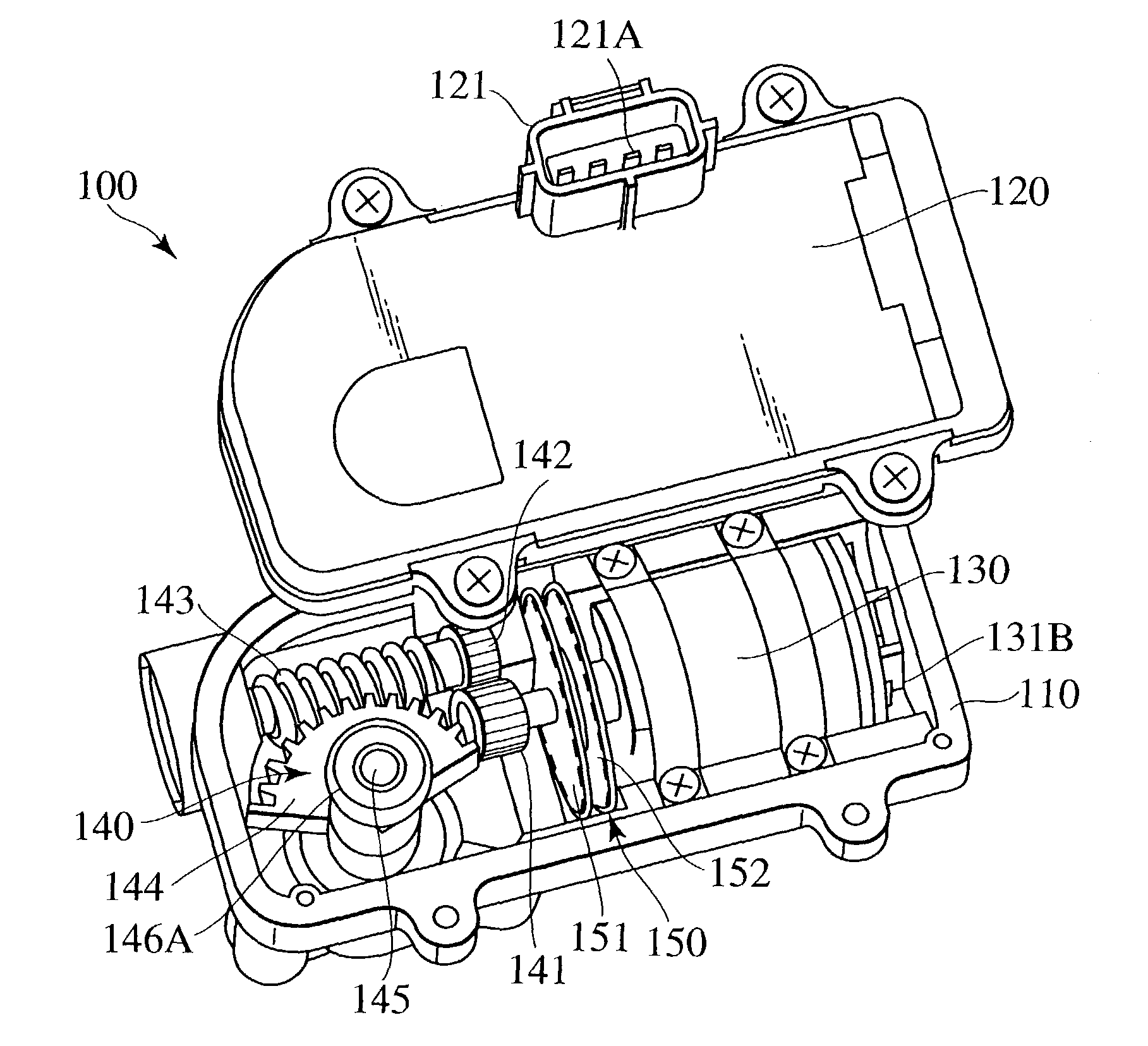
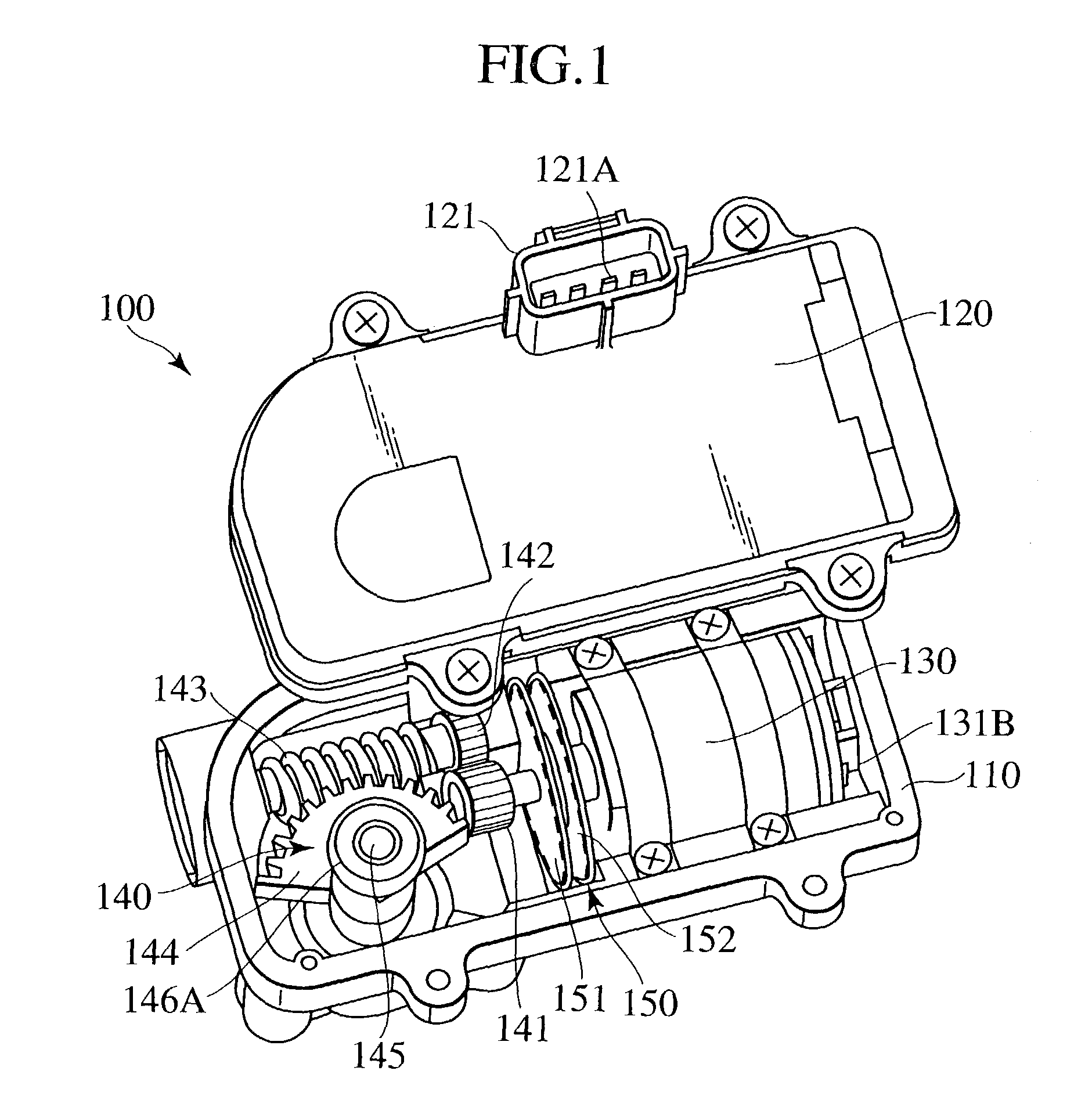
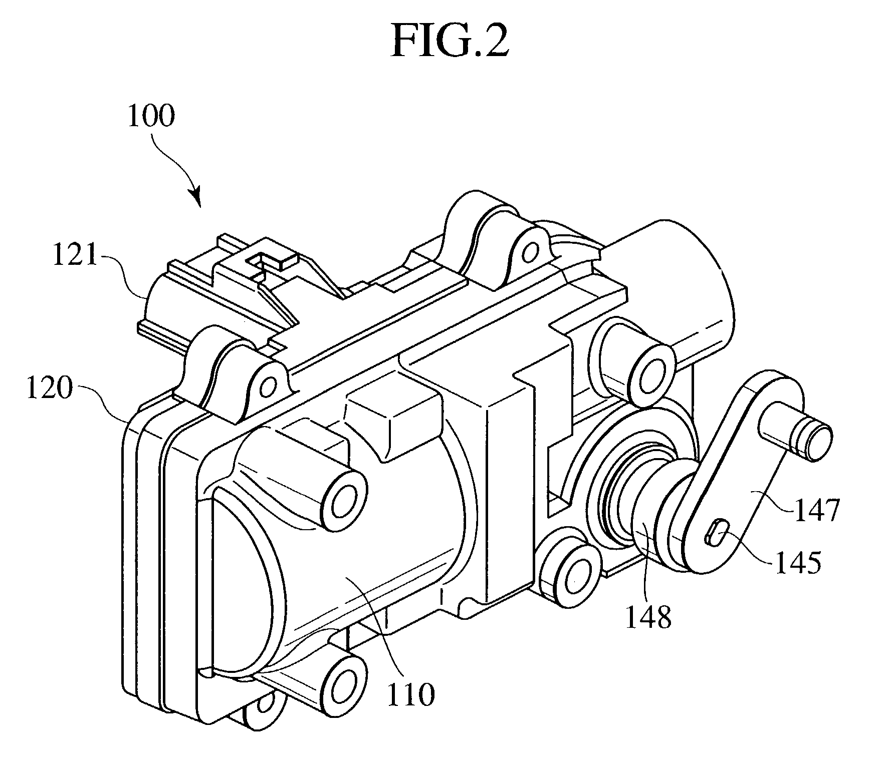
[0047]Referring to FIG. 1, the electronically controlled actuator 100 in the preferred embodiment comprises a body 110, a cover 120, a motor 130, a speed change mechanism 140, and a position sensor 150. The motor 130, the speed change mechanism 140 and the position sensor 150 are arranged in a space between the body 110 and the cover 120.

[0048]Bands and screws fasten the motor 130 to the body 110. A power supply connector 121 is formed integrally with the cover 120. The motor 130 is a dc motor with brushes by way of example.

[0049]The speed change mechanism 140 comprises a pinion 141, a gear 142, a worm 143, a worm wheel 144, and an output shaft 145. The pinion 141 is fixedly mounted on the output shaft of the motor 130 by press fitting. The pinio...


PUM


Abstract

An electronically controlled actuator for controlling a turbocharger has a motor, a speed change mechanism and a position sensor contained in a case consisting of a body and a cover. The driving force of the motor is transmitted through the speed change mechanism to an output shaft to drive the movable vanes of a turbocharger for turning. A first bearing supporting the output shaft for rotation is held on the cover, and a second bearing supporting the output shaft for rotation is held on the body. The position sensor is mounted on the output shaft of the motor. The reliability of the actuator is improved.

Description

BACKGROUND OF THE INVENTION[0001]The present invention relates to an electronically controlled actuator, and more particularly, to an electronically controlled actuator suitable for the positional control of the movable vanes of a variable-capacity turbocharger for an automotive internal combustion engine.[0002]A prior art electronically controlled actuator disclosed in, for example, EP-A No. 109088 / 1999 includes a motor and a speed change mechanism. In this prior art electronically controlled actuator, one end of an output shaft included in the speed change mechanism is connected to a driven member and the other end of the same is provided with a position sensor. The position sensor measures the present working position of the actuator and provides data to be used for the feedback control of the working position. The output shaft is supported for rotation in two bearings. The motor and the speed change mechanism are held in a case having a body and a cover.[0003]Since one end of th...

Claims


Application Information

Patent Timeline
IPC IPC(8): F04B17/00F04B35/00F02B37/24H02K5/22H02K7/06H02K7/116H02K11/00
CPCH02K7/1166F02B37/24H02K5/225H02K7/06H02K11/00F02B37/186Y02T10/12
Inventor SUGANAMI, MASAYUKISAEKI, HIROAKIYAMADA, SHIGEKI
Owner HITACHI LTD
Why Eureka
Try Eureka