Quality control system for irradiation apparatus

a quality control system and irradiation apparatus technology, applied in calibration apparatus, radiation beam directing means, instruments, etc., can solve the problems of unsatisfactory reliability of measurement of optical path deviation and deterioration of radiotherapy operation efficiency, and achieve accurate and accurate results.

Inactive Publication Date: 2007-07-24
FUJIFILM HLDG CORP +1
View PDF10 Cites 12 Cited by
  • Summary
  • Abstract
  • Description
  • Claims
  • Application Information

AI Technical Summary

Benefits of technology

[0013]In the quality control system for an irradiation apparatus in accordance with the first aspect of the present invention, radiation energy is stored in the areas of the stimulable phosphor panel exposed to the position check radiation and to the position check light in different levels, whereby the relation between the irradiating position of the position check radiation and the irradiating position of the position check light can be obtained by reading the radiation image on the stimulable phosphor panel. Accordingly, factors deteriorating the accuracy of obtaining the relative positions such as adjustment of the alignment of the central hole in the X-ray film and the center of the bundle of the position check light, can be removed, whereby the relative positions can be more accurately obtained from the radiation image, and the reliability and the efficiency of checking the optical path deviation is within the tolerance where the deviation does not cause any trouble in the radiotherapy.
[0014]In the quality control system for an irradiation apparatus in accordance with the second aspect of th...

Problems solved by technology

However, it is troublesome operation to accurately position the X-ray film so that the central hole is aligned with the center of the bundle of the position check ligh...

Method used


Image

  • Quality control system for irradiation apparatus
  • Quality control system for irradiation apparatus
  • Quality control system for irradiation apparatus

Examples


Embodiment Construction

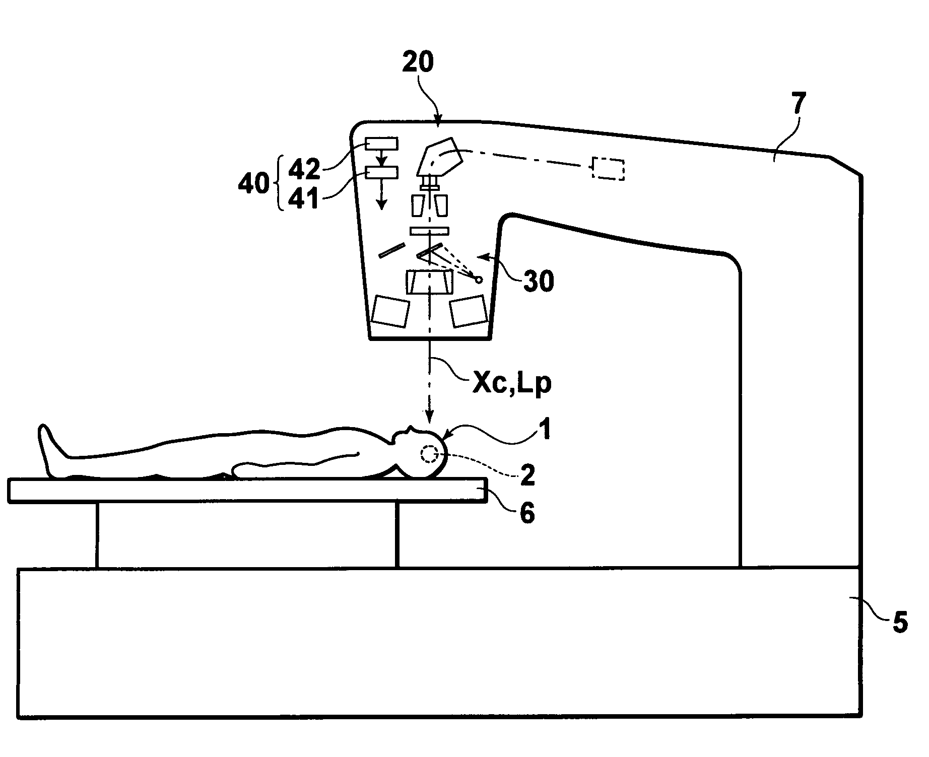
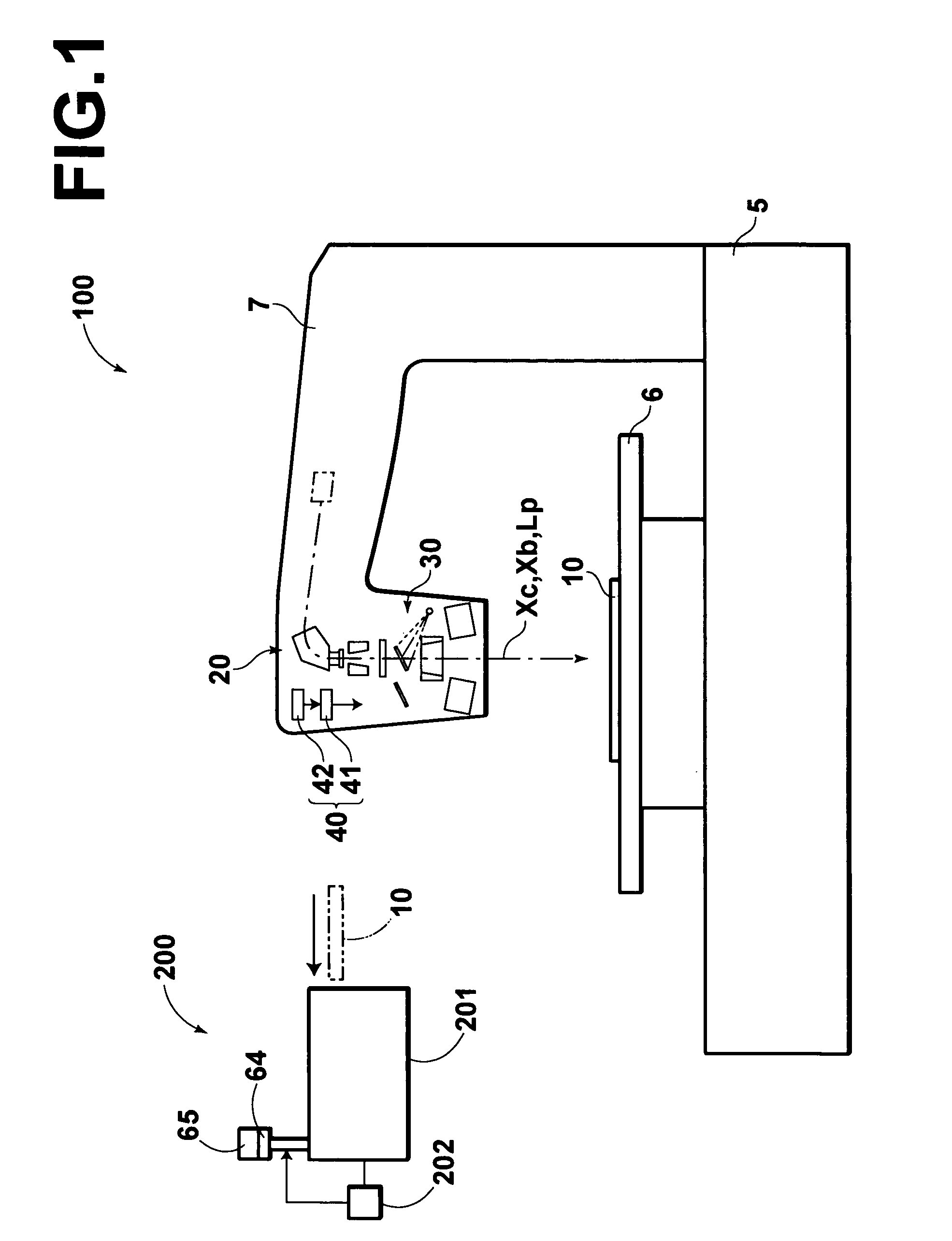
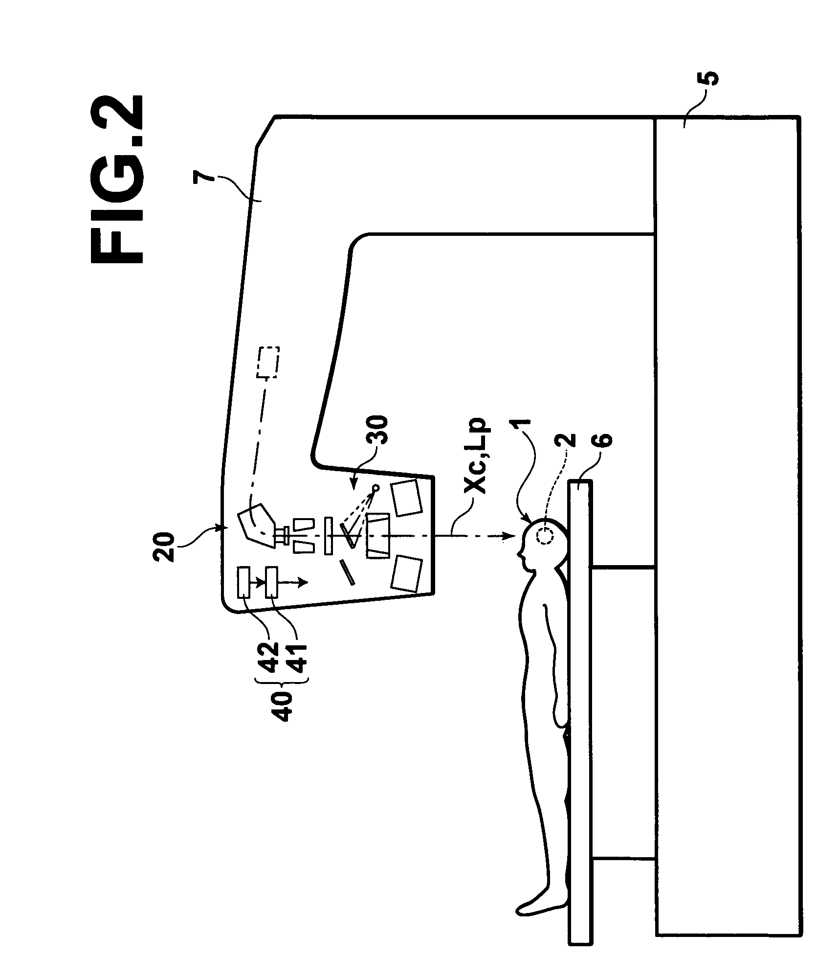
[0027]A quality control system 200 in accordance with an embodiment of the present invention comprises a radiation image reading system 201 which reads out a radiation image from a stimulable phosphor panel 10 which is disposed in a predetermined position in a radiotherapy system (an irradiation apparatus) 100 to receive irradiation of position check radiation Xc from an irradiation system 20 of the radiotherapy system 100 and irradiation of uniform radiation Xb from the irradiation system 20 to an area larger than the area exposed to the position check radiation Xc and to receive irradiation of position check light Lp in a visible region from a position check light irradiation system 30 after receiving the irradiation of the uniform radiation Xb, thereby forming a radiation image, and a relative position obtaining system 202 which obtains the relation between the irradiating position of the position check radiation Xc and the irradiating position of the position check light Lp on t...


PUM


Abstract

A quality control system for an irradiation apparatus includes a radiation image reading system. The radiation image reading system reads out a radiation image from a stimulable phosphor panel which is disposed in a predetermined position to receive irradiation of position check radiation from an irradiation system and irradiation of uniform radiation from the irradiation system to an area larger than the area exposed to the position check radiation and to receive irradiation of position check light in a visible region from a position check light irradiation system after receiving the irradiation of the uniform radiation and to form a radiation image. A relative position obtaining system obtains the relation between the irradiating position of the position check radiation and the irradiating position of the position check light on the basis of the radiation image read by the radiation image reading system.

Description

BACKGROUND OF THE INVENTION[0001]1. Field of the Invention[0002]This invention relates to a quality control system for an irradiation apparatus, and more particularly to a quality control system for checking a position exposed to the radiation in an irradiation apparatus.[0003]2. Description of the Related Art[0004]There have been known a radiotherapy system in which a lesion is treated by concentrating radiation on the lesion, as disclosed, for instance, in Japanese Utility Model Publication No. 2593412 and “Zukai Shinryo-hoshasen Gijutu Jissen Gaido (Illustrated Radiodiagnosis Practice Guide)” (2002) Kabushiki Gaisha Kobundo. In such a system, after the position of the lesion is adjusted so that the lesion is on the optical path of a position check light which is arranged to propagate along the same optical path as the treatment radiation, the treatment radiation is applied to the lesion, whereby the treatment radiation is accurately applied to the lesion.[0005]The tolerance of th...

Claims


Application Information

Patent Timeline
IPC IPC(8): A61B6/08G01N23/04G03B42/08G11B7/135G12B13/00A61N5/10G01T1/29
CPCG01T1/2014
Inventor ARAKAWA, SATOSHI
Owner FUJIFILM HLDG CORP
Why Eureka
Try Eureka