Servo writing a disk drive from spiral tracks by shifting a demodulation window an integer number of sync mark intervals

Inactive Publication Date: 2007-07-24
WESTERN DIGITAL TECH INC
View PDF25 Cites 142 Cited by
  • Summary
  • Abstract
  • Description
  • Claims
  • Application Information

AI Technical Summary

Benefits of technology

[0008]The present invention may be regarded as a method of writing product servo sectors to a disk of a disk drive. The disk drive comprises control circuitry and a head disk assembly (HDA) comprising the disk, an actuator arm, a head coupled to a distal end of the actuator arm, and a voice coil motor for rotating the actuator arm about a pivot to position the head radially over the disk. The disk comprises a plurality of spiral tracks, wherein each spiral track comprises a high frequency signal interrupted by a sync mark at a sync mark interval. The head internal to the disk drive is used to read the spiral tracks to generate a read signal. The read signal is processed to detect the sync marks in the spiral tracks to synchronize a servo write clock. The servo write clock is used to open a demodulation window during which the high frequency signal in the spiral tracks is demodulated to generate a position error signal used to maintain the head internal to the disk drive along a first servo track. The head internal to the disk drive is used to write product servo sectors along the first servo track. The demodulation window is then shifted by an integer number of sync mark intervals to initiate a seek to a second servo track. The head internal to the disk drive is used to write product servo sectors along the second servo track.
[0009]In one embodiment, the demodulation window is shifted by one sync mark, and in another embodiment, more than one sync mark.
[0010]In another embodiment, the step of demodulating the high frequency signal in the spiral tracks comprises the step of demodulating the high frequency signal into a plurality of servo burst signals. In one embodiment, the step of generating the position error signal comprises the step of computing a difference between the servo burst signals. In one embodiment, the step of shifting the demodulation window an integer number of sync mark intervals causes the plurality of servo burst signals to shift a corresponding amount to generate a non-zero position error signal.
[0011]In yet another embodiment, the step of demodulating the high frequency signal in the spiral tracks comprises the step of integrating the re

Problems solved by technology

However, external servo writers are expensive and require a clean room environment so that a head positioning pin can be inserted into the head disk assembly (HDA) without contaminating the disk.
Thus, external servo writers have become an expensive bottleneck in the disk drive manufacturing process.
However, the '679 patent does not disclose how to seek from a current servo track to a next servo track during the servo writing operation.

Method used


Image

  • Servo writing a disk drive from spiral tracks by shifting a demodulation window an integer number of sync mark intervals
  • Servo writing a disk drive from spiral tracks by shifting a demodulation window an integer number of sync mark intervals
  • Servo writing a disk drive from spiral tracks by shifting a demodulation window an integer number of sync mark intervals

Examples


Embodiment Construction

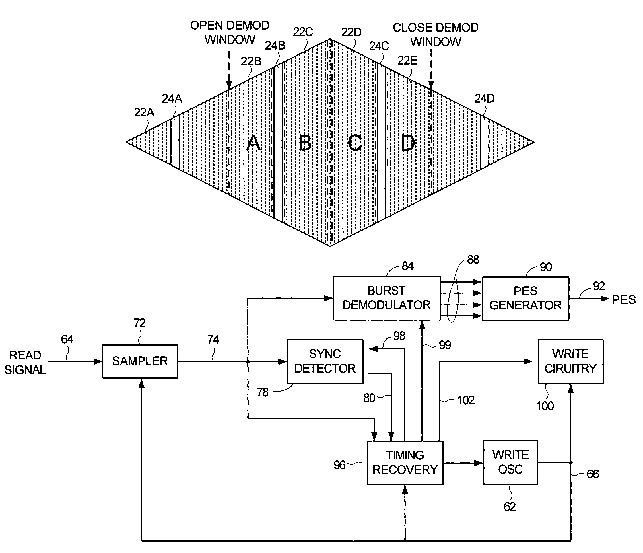
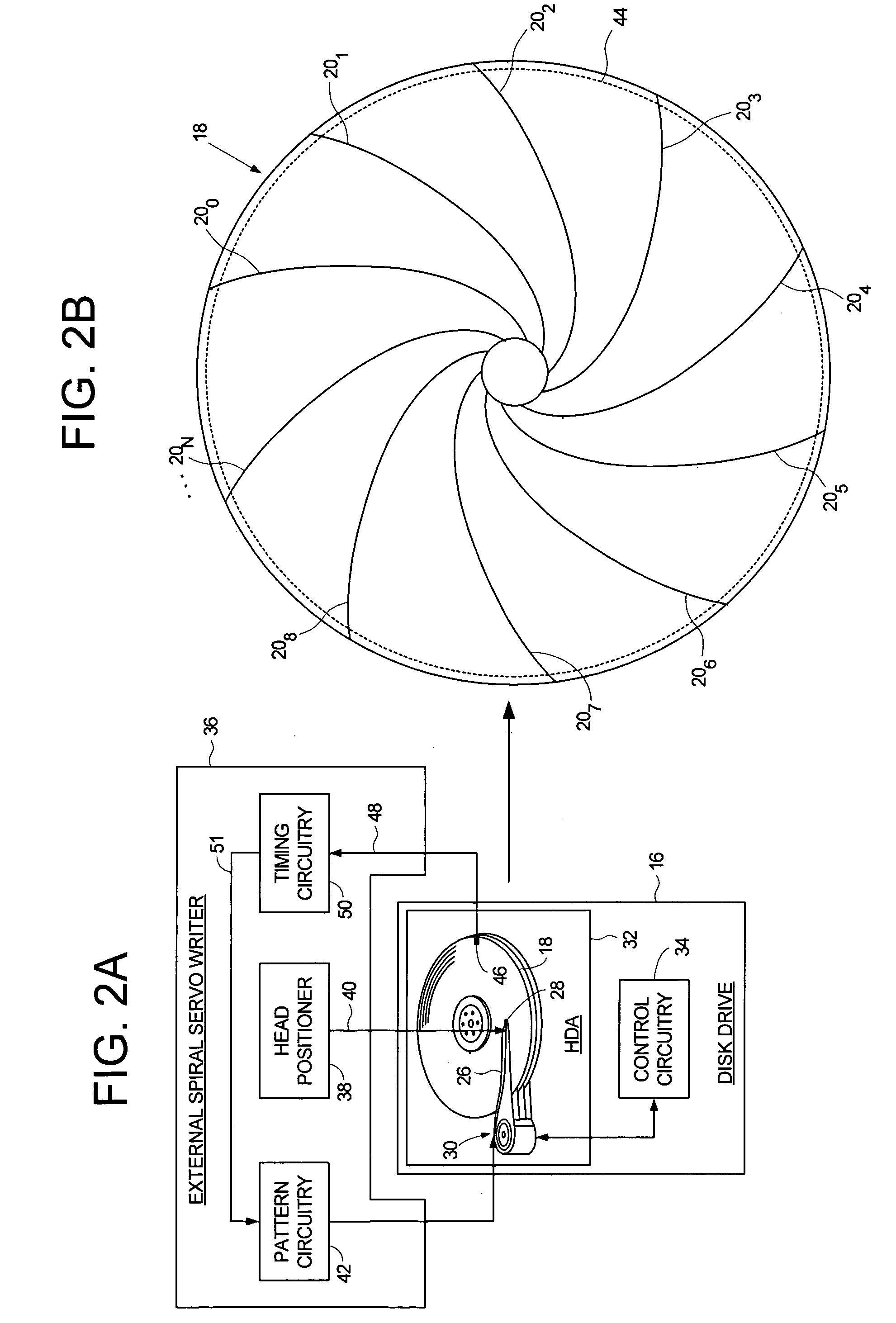
[0031]FIGS. 2A and 2B show an embodiment of the present invention wherein a plurality of spiral tracks 200-20N are written to a disk 18 of a disk drive 16 using an external spiral servo writer 36 (in an alternative embodiment, the spiral tracks are stamped onto the disk using magnetic printing techniques). The disk drive 16 comprises control circuitry 34 and a head disk assembly (HDA) 32 comprising the disk 18, an actuator arm 26, a head 28 coupled to a distal end of the actuator arm 26, and a voice coil motor 30 for rotating the actuator arm 26 about a pivot to position the head 28 radially over the disk 18. A write clock is synchronized to the rotation of the disk 18, and the plurality of spiral tracks 200-20N are written on the disk 18 at a predetermined circular location determined from the write clock. Each spiral track 20i comprises a high frequency signal 22 (FIG. 4B) interrupted by a sync mark 24 at a sync mark interval.

[0032]The external spiral servo writer 36 comprises a h...


PUM


Abstract

A method of writing product servo sectors to a disk of a disk drive is disclosed. The disk comprises a plurality of spiral tracks, wherein each spiral track comprises a high frequency signal interrupted by a sync mark at a sync mark interval. The sync marks in the spiral tracks are detected to synchronize a servo write clock used to open a demodulation window during which the high frequency signal in the spiral tracks is demodulated to generate a position error signal for maintaining the head along a first servo track while writing product servo sectors along the first servo track. The demodulation window is then shifted by an integer number of sync mark intervals to initiate a seek to a second servo track. The head is then used to write product servo sectors along the second servo track.

Description

BACKGROUND OF THE INVENTION[0001]1. Field of the Invention[0002]The present invention relates to disk drives for computer systems. More particularly, the present invention relates to a servo writing a disk drive from spiral tracks by shifting a demodulation window an integer number of sync mark intervals.[0003]2. Description of the Prior Art[0004]When manufacturing a disk drive, servo sectors 20-2N are written to a disk 4 which define a plurality of radially-spaced, concentric data tracks 6 as shown in the prior art disk format of FIG. 1. Each data track 6 is partitioned into a plurality of data sectors wherein the servo sectors 20-2N are considered “embedded” in the data sectors. Each servo sector (e.g., servo sector 24) comprises a preamble 8 for synchronizing gain control and timing recovery, a sync mark 10 for synchronizing to a data field 12 comprising coarse head positioning information such as a track number, and servo bursts 14 which provide fine head positioning information...

Claims


Application Information

Patent Timeline
IPC IPC(8): G11B21/02
CPCG11B20/10222G11B20/12G11B20/14G11B5/59655G11B5/59661G11B5/59666G11B2020/10916G11B2020/1281G11B2020/1287G11B2020/1484G11B2220/2516
Inventor WEERASOORIYA, SIRI S.LEE, TEHRI S.
Owner WESTERN DIGITAL TECH INC
Why Eureka
Try Eureka