Sound enhancement system

a technology of enhancement system and sound, which is applied in the direction of electrophonic musical instruments, instruments, stereo circuit arrangements, etc., can solve the problems of lack of realism, graininess, high frequency distortion of media, etc., and achieve the effects of enhancing mono-channel input signals, enhancing multi-channel input signals, and enhancing stereo imagery of input signals

Active Publication Date: 2007-07-24
PACKARD THOMAS NELSON
View PDF11 Cites 4 Cited by
  • Summary
  • Abstract
  • Description
  • Claims
  • Application Information

AI Technical Summary

Benefits of technology

[0008]a system for enhancing monaural input signal including a plurality of loudspeakers or recording channels for reproduction of signal, at least one device each having an input terminal for receiving the monaural input signal, a square root filter that generates artificial high frequency overtones from the input signal, and an output terminal that receives signal from the square root filter and that provides an output signal, such that the signals are provided to one or more loudspeaker or recording channel to create a pseudo-stereo effect based on differences between said output signals.
[0009]a system for enhancing multi-channel input signals including a plurality of loudspeakers or recording channels for reproduction of signal, at least one device each having an input terminal for receiving at least one of the input signals, a square root filter that generates artificial high frequency overtones from the signal at the input terminal, and an output terminal that receives signal from the square root filter and that provides an output signal, such that the output signal is provided to one or more loudspeaker or recording channel to enhance the stereo imagery of the input signals.
[0010]a method for enhancing the fidelity of sound by a sound enhancement device including an input terminal for receiving input signal from a microphone or recorded medium in which the input signal is represented by a constantly varying waveform having a plurality of slopes and at least one amplitude, and also including an output terminal for providing enhanced sound signal to a loudspeaker or recording channel comprising the steps of splitting the input signal into frequency ranges, distorting the signals from one or more frequency ranges by exaggerating slopes while maintaining the same amplitude to create processed signals containing artificial overtones, and combining the processed signals and signals from frequency ranges that have not been processed to deliver the input signal plus artificial overtones to the output terminal.
[0011]a method for enhancing the fidelity of sound by a sound enhancement device including an input terminal for receiving input signal from a microphone or recorded medium and an output terminal for providing enhanced sound signal to a loudspeaker or recording channel comprising the steps of creating artificial overtones from the input signal, maintaining the level of artificial overtones to track proportionally and automatically the level of the input signal, and mixing the maintained level of artificial overtones with the input signal.
[0012]a method for enhancing the fidelity of sound by a sound enhancement device including an input terminal for receiving input signal from a microphone or recorded medium and an output terminal for providing enhanced sound signal to a loudspeaker or recording channel comprising the steps of detecting an attack transient in the input signal and producing a momentary gain increase of the input signal upon detection of an attack transient.
[0013]a method for enhancing the fidelity of sound by a sound enhancement device including an input terminal for receiving input signal from a microphone or recorded medium and an output terminal for providing enhanced sound signal to a loudspeaker or recording channel comprising the steps of splitting the input signal into frequency ranges, detecting attack transients occuring in one or more frequency ranges, producing momentary gain increases of frequency range signal upon detection of attack transients to create processed signal, and combining the frequency ranges that have been processed with those that have not been processed to deliver a combined signal to the output terminal.

Problems solved by technology

Yet even the latest technology has some sort of defect, which the human ear, being a precise instrument, interprets as lack of realism.
Defects in the earliest recordings, specifically Edison cylinders and 78 RPM records, comprise foreign particles or scratches in the recording matrix which upon playback produce discrete clicks or pops, and graininess in the recording matrix which is visible under magnification, which upon playback produces high frequency “hiss.” With the advent of long play 33⅓ RPM record and magnetic tape, the issue of foreign particles was substantially eliminated, but these media are still susceptible to graininess producing hiss and high frequency distortion during playback.
With the advent of the compact disc, the graininess issue was resolved by digital recording techniques but the low sampling rate resulted in limited bandwidth whose sound some have characterized as having sterility or lack of presence.
Another type of defect detracting from aural realism involves the compromises in microphone placement utilized in detecting the sound.
Microphones that are distant from the origin of the sound are overly sensitive to hall echo.
Use of a close microphone alone might improve attack transients, but commensurate use of multi-microphoning to rid the recorded sound of unnatural dryness results in a plurality of mixed phases that likewise have a blurring effect.
Another cause of blurring is the use of multiple loudspeakers, increasingly common in live music concerts, public theaters, or home theaters.
The listener is aware of a surround-sound effect but the use of multiple loudspeakers does not improve and may even interfere with spacial location discernment.
Another cause of high frequency overtone or attack transient loss is in the wireless transmission of sound where high frequencies and attack transients are deliberately removed from the transmitted signal in order that the transmission does not interfere with another wireless tranmission being broadcast at a nearby carrier frequency.
Yet another cause of high frequency overtone or attack transient loss is mechanical inertia associated with microphone or loud speaker diaphrams, cutting or reproducing styli, or the like.
Prior art devices do not compensate for absence of overtones or attack transients, one or both sound characteristics being necessary ingredients for aural realism.

Method used


Image

  • Sound enhancement system
  • Sound enhancement system
  • Sound enhancement system

Examples


Embodiment Construction

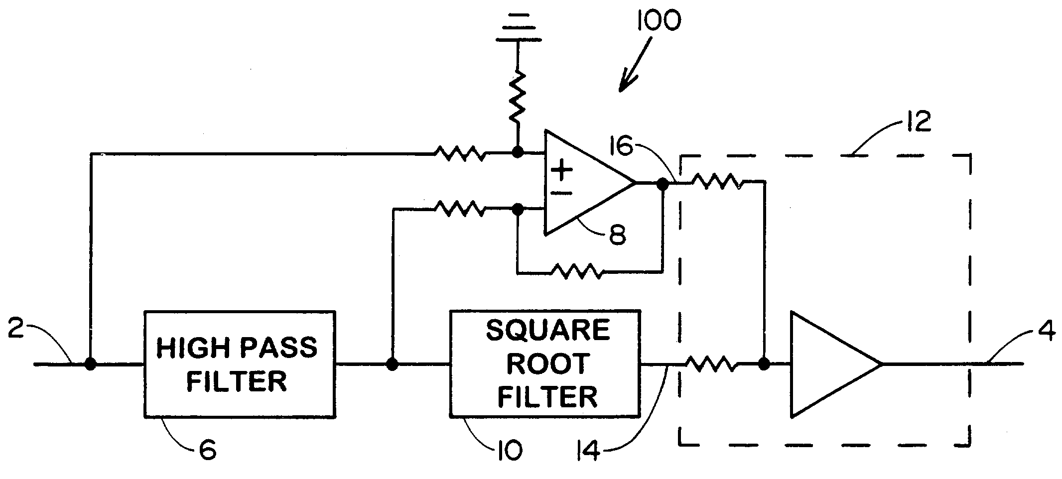
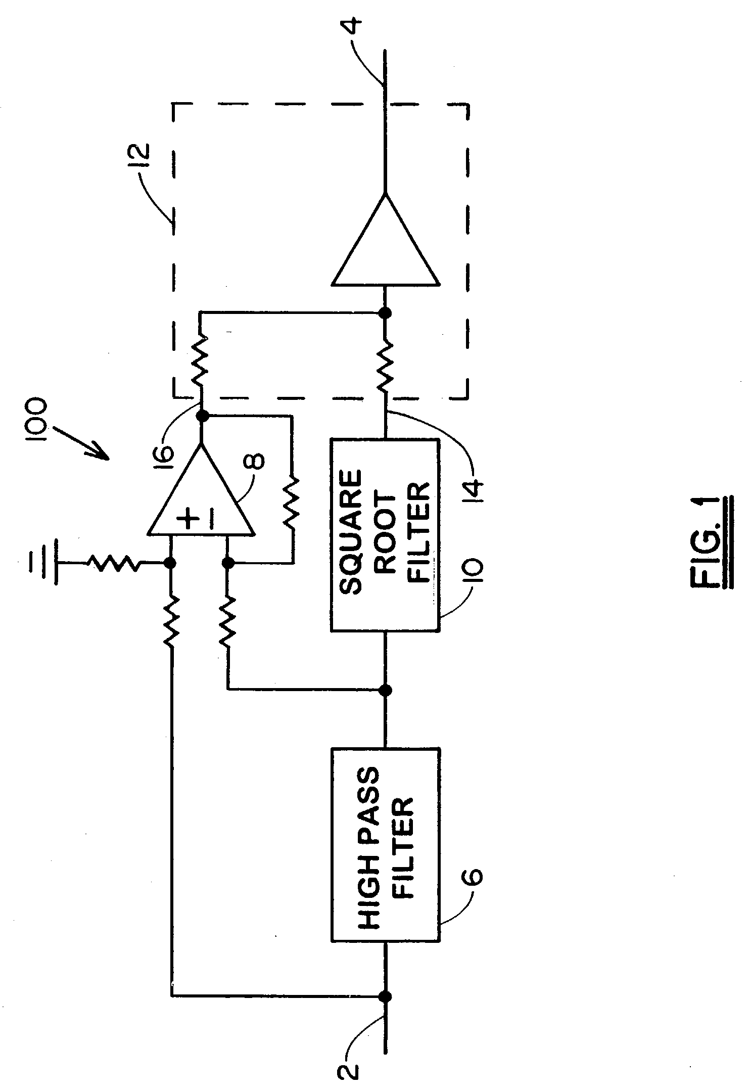
[0023]Referring to FIG. 1, an input terminal 2 of the sound enhancement system 100 receives electrical signal, or “input signal” from a microphone or recorded medium. Input terminal 2 is connected to a high pass filter 6 which in turn is connected to a square root filter 10 that provides signal to a first input 14 of summer 12. Complementary filter 8 receives signal from input terminal 2 and may receive subtractive signal from high pass filter 6 as shown. The complementary filter 8 passes input signals that are not passed by high pass filter 6, that is, complementary filter 8 is essentially a low pass filter. The output of complementary filter 8 comprises the signal at the second input 16 of summer 12. The output of summer 12 is connected to the output terminal 4 of sound enhancement system 100. The instantaneous signal from square root filter 10 varies as the square root of the instantaneous signal from high pass filter 6. For a high pass filter 6 output signal represented by the e...


PUM


Abstract

A system for enhancing sound quality comprising a filter that square roots the instantaneous amplitude of frequencies in an input signal for generating artificial harmonics corresponding to said frequencies. The system can comprise an automatic level control that momentarily boosts the amplitude of artificially generated harmonics to emphasize attack transients occuring within the input signal.

Description

FIELD OF THE INVENTION[0001]This invention pertains to the field of sound reproduction devices, and in particular to a sound enhancement device that imparts overtones and transient attack sounds.BACKGROUND OF THE INVENTION[0002]The recording industry has gone through a number of technologies, successors either affording greater convenience to the user such as longer playing time, and preferrably duplicating the live performance more faithfully. Yet even the latest technology has some sort of defect, which the human ear, being a precise instrument, interprets as lack of realism. Defects in the earliest recordings, specifically Edison cylinders and 78 RPM records, comprise foreign particles or scratches in the recording matrix which upon playback produce discrete clicks or pops, and graininess in the recording matrix which is visible under magnification, which upon playback produces high frequency “hiss.” With the advent of long play 33⅓ RPM record and magnetic tape, the issue of fore...

Claims


Application Information

Patent Timeline
Patent Type & Authority Patents(United States)
IPC IPC(8): H03G3/00G10H1/16H04R5/04
CPCG10H1/16H04R5/04G10H2210/031G10H2250/131
Inventor PACKARD, THOMAS NELSON
Owner PACKARD THOMAS NELSON
Why Eureka
Try Eureka