Method for radio transmission in an alarm signaling system

a radio transmission and alarm signaling technology, applied in the field of radio transmission of messages, can solve the problems of saving expensive electricity in all other subscribers

Active Publication Date: 2007-07-24
SIEMENS SWITZERLAND
View PDF17 Cites 0 Cited by
  • Summary
  • Abstract
  • Description
  • Claims
  • Application Information

AI Technical Summary

Benefits of technology

[0008]The object of the present invention is therefore to specify a method in a radio alarm signaling system which in the bidirectional network allows a unidirectional subscriber to use any bidirectional network subscriber as an intermediate station or router in each case, without an avalanche of telegrams being initiated via of the bidirectional subscribers which could lead to a system becoming overloaded.
[0014]The method in accordance with the invention thus ensures that, of all the bidirectional subscribers that have received the message, only a single subscriber, namely the one which is first in line according to its wait time, confirms or forwards the message. All the others receive this confirmation or forwarding message and then suppress their own forwarding. This keeps the load on the radio channel to a minimum. Since in each case only one bidirectional subscriber has a telegram to transmit, expensive electricity in all other subscribers is saved. Nor is any mechanism for resolving collisions triggered, therefore, the reaction time of the system remains short for example for the activation and deactivation mentioned above. Nor is any increased expense involved in the unidirectional element. It does not require additional input elements nor more memory space than a conventional transmitter.
[0015]Preferably the wait times of the individual subscribers can be defined in the system so that the central station confirms receipt as the first subscriber. This also reduces the reaction time of the system to a minimum. In addition the order of the time slots and thereby the wait times of all bidirectional subscribers can be defined by their address within the radio cell.

Problems solved by technology

Since in each case only one bidirectional subscriber has a telegram to transmit, expensive electricity in all other subscribers is saved.

Method used


Image

  • Method for radio transmission in an alarm signaling system
  • Method for radio transmission in an alarm signaling system
  • Method for radio transmission in an alarm signaling system

Examples


Embodiment Construction

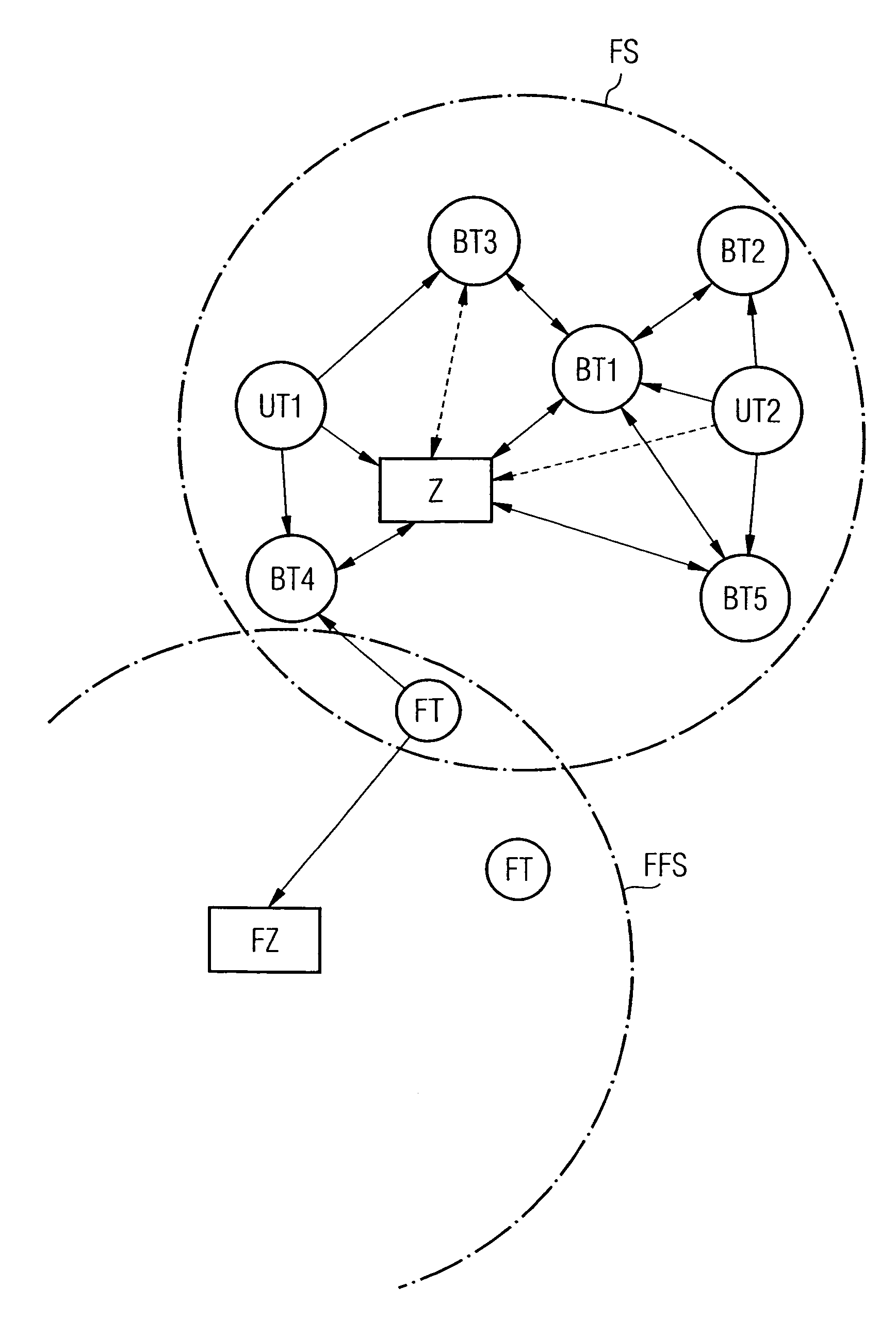
[0021]The radio system FS shown in FIG. 1 consists of a central station Z, a number of bidirectional subscribers BT1 to BT5 and individual unidirectional subscribers UT1 and UT2. Provided the radio coverage allows this, the individual bidirectional subscribers BT1, BT4 and BT5 can make direct contact with the central station, in some cases with each other as well. The drawing shows the possible direct radio connections as solid arrows whereas the connections which are not possible—because the radio range is too small or because of a fault—are shown as dotted arrows. Where this direct contact is not possible because of the range or because of a fault, such as for example between BT2 and BT3, contact will be established via a router, that is an intermediate station. In the example shown subscriber BT1 is such a router. The unidirectional subscribers UT1 and UT2 in the example only have a transmitter and can thus only issue messages. Provided they are in a radio range of the central st...


PUM


Abstract

In a radio alarm signaling system with a central station (Z) and a plurality of bidirectional (BT1 to BT5) and unidirectional (UT1, UT2) subscribers, the unidirectional subscribers (UT1, UT2) attempt to send messages via one of the bidirectional subscribers (BT1 to BT5) to the central station. In this case the message sent by a unidirectional subscriber (UT2) is received by all bidirectional subscribers (BT1, BT2, BT5) in its radio coverage area. Each bidirectional subscriber that has received this message waits until a time slot individually assigned to it before forwarding the message. During the wait time each of these bidirectional subscribers (BT1, BT2, BT5) monitors the radio channel to see whether another subscriber has already forwarded the message. If this is the case it suppresses its own forwarding. This ensures that only one of the bidirectional subscribers (BT1) forwards the message so that no overloading of the radio system occurs.

Description

PRIORITY[0001]This application claims priority to German application no. 103 17 586.5 filed Apr. 16, 2003.TECHNICAL FIELD OF THE INVENTION[0002]The present invention relates to a method for radio transmission of messages in an alarm signaling system with a central station and a plurality of bidirectional and unidirectional subscribers, with the central switch and the bidirectional subscribers each featuring send and receive equipment while the unidirectional subscribers merely possess a send unit.BACKGROUND OF THE INVENTION[0003]Alarm signaling systems in which the messages are transmitted by radio provide the user with many advantages. The alarm signaling systems in this case comprise signaling sensors as subscribers or ancillary stations which, when a danger is detected, for example a fire or break-in, send an alarm message via a radio link to a central station (which should also be taken to mean repeaters) in which, to remedy the danger, further measures such as sending an alarm ...

Claims


Application Information

Patent Timeline
Patent Type & Authority Patents(United States)
IPC IPC(8): H04M11/04G08B25/00G08B25/01G08B25/10
CPCG08B25/009G08B25/014G08B25/10G08B25/007
Inventor SCHREYER, KARLHEINZSCHROPP, WERNER
Owner SIEMENS SWITZERLAND
Why Eureka
Try Eureka