Water-cooling heat dissipation device

a heat dissipation device and water cooling technology, which is applied in the direction of lighting and heating apparatus, instruments, and semiconductor/solid-state device details, etc., can solve the problems of affecting the development of compact computers, occupying lots of installation space, and affecting the heat dissipation efficiency of computers, etc., to achieve the effect of increasing the heat dissipation area, enhancing heat dissipation efficiency, and increasing the water flow ra

Active Publication Date: 2007-07-31
CHEMTRON RES
View PDF9 Cites 42 Cited by
  • Summary
  • Abstract
  • Description
  • Claims
  • Application Information

AI Technical Summary

Benefits of technology

[0005]The present invention provides a water-cooling heat dissipation device directly using a housing to conduct heat so that a compact structure to reduce cost, weight and volume is obtained.
[0008]The passage can be formed by a plurality of apertures, protruded columns or vortex slots on the bottom of the recess to increase heat exchanging area. The circulator includes rotator component, a retainer component and a stator component. The rotator component includes a magnetic pole and an impeller, and the stator component includes a circuit board, a coil and a core. The impeller is located right above the passage so that during the rotation of the impeller, the water flowing rate can be increased to enhance the heat exchanging efficiency.

Problems solved by technology

As the computer is more powerful with high speed CPU, heat dissipation issue is more serious to be concerned as how to keep the CPU at a proper temperature so that the computer can work reliably.
The bulk volume will occupy lots of installation space to impede compact development of the computer.

Method used


Image

  • Water-cooling heat dissipation device
  • Water-cooling heat dissipation device
  • Water-cooling heat dissipation device

Examples


Embodiment Construction

[0021]Reference will now be made in detail to the preferred embodiments of the present invention, examples of which are illustrated in the accompanying drawings. Wherever possible, the same reference numbers are used in the drawings and the description to refer to the same or like parts.

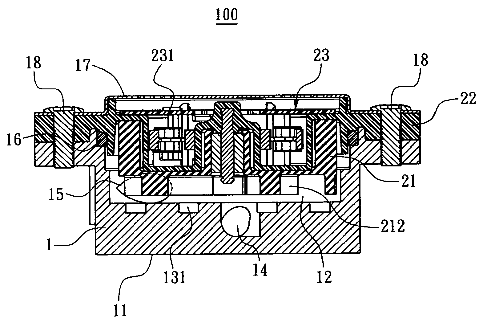
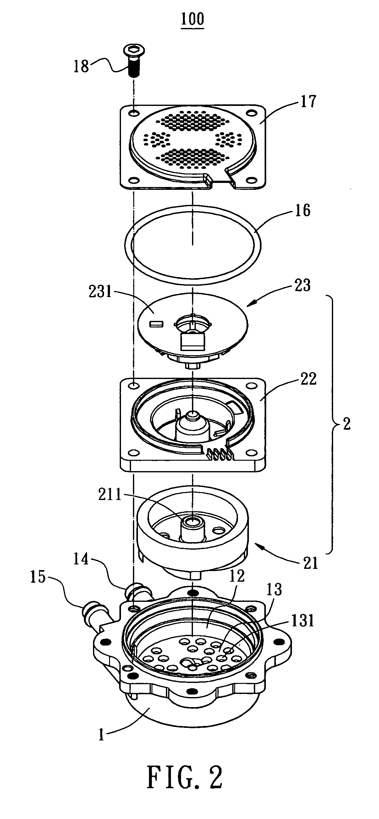
[0022]Referring to FIGS. 2 and 3, a water-cooling heat dissipation device 100 of the present invention can be used for a CPU, such as shown in FIG. 7. The water-cooling heat dissipation device 100 includes a housing 1 and a water circulator 2. A bottom surface 11 of the housing 1 for contact with the CPU 200 is made of heat conductive material such as copper or aluminum. Or, the whole housing 1 can be made of heat conductive material such as metal.

[0023]The housing 1 includes a recess 12. In this preferred embodiment, a plurality of apertures 131 are formed on the bottom of the recess 12 as a water passage 13. The water circulator 2 includes a rotor component 21, a retainer component 22 and a stator ...


PUM


Abstract

A heat dissipation system includes a housing, a circulator and a cooler. The housing has at least one surface made of heat-conductive metal to contact with a heat source. The housing includes a recess with a passage formed on the bottom to contain cooling liquid and an inlet and an outlet connected to the recess. Two pipes are provided to connected between the inlet and the outlet and the cooler, respectively. The circulator is installed in the recess to circulate the flowing of the cooling liquid. As such, heat generated from the heat source is directly conducted to the housing and takes away by the cooling liquid circulated by the circulator to the cooler.

Description

BACKGROUND OF THE INVENTION[0001]The present invention relates in general to a water-cooling heat dissipation device, and more particularly, to the water-cooling heat dissipation device applied to a heat-generating device such as a central processing unit (CPU).[0002]As the computer is more powerful with high speed CPU, heat dissipation issue is more serious to be concerned as how to keep the CPU at a proper temperature so that the computer can work reliably.[0003]FIG. 1 shows a conventional water-cooling heat dissipation system 100a used for a CPU. As shown, the heat dissipation system 100a includes a heat sink 10a mounted on a CPU 200a, a water pump 20a, a cooler 30a and a water tank 40a. The heat sink 10 has a water outlet 101a and a water inlet 102a. A pipe 103a is connected between the water inlet 102a and a water outlet 201a of the water pump 20a. Another pipe 104a is connected between the water outlet 101a and a water inlet 301a of the cooler 30a. The cooler 30a is composed o...

Claims


Application Information

Patent Timeline
Patent Type & Authority Patents(United States)
IPC IPC(8): F28D15/00
CPCG06F1/20G06F2200/201H01L23/473H01L2924/0002H01L2924/00
Inventor DUAN, QIANG-FEI
Owner CHEMTRON RES
Why Eureka
Try Eureka