Position-coding pattern

a position-coding pattern and pattern technology, applied in the field of position-coding pattern, can solve the problems of discontinuous position-coding pattern on the base, inability to perform the function intended by the user, and undesirable boundary areas without position-coding pattern

Active Publication Date: 2007-07-31
ANOTO IP LIC
View PDF11 Cites 46 Cited by
  • Summary
  • Abstract
  • Description
  • Claims
  • Application Information

AI Technical Summary

Benefits of technology

[0017]An object of the present invention thus is to make it possible for a user unit having a limited storage capacity to handle templates for bases with position-coding patterns.
[0018]Another object of the present invention is to provide bases with position-coding patterns, which can be read correctly using a user unit which has a displacement between on the one hand a pen point that can be used to make marks on the base and, on the other hand, a sensor which records the position code.
[0022]The first position code extending over the surface enables position determination over the entire surface. It also makes it possible for a user unit to electronically record information written on the surface by means of a pen point of the user unit. The first position code can be said to correspond to the continuous position-coding pattern mentioned by way of introduction.
[0023]The second position code makes it possible to mark on the surface one or more fields so that a user unit electronically can detect that its pen point is located in a certain field on the surface and that a determined function thus is to be performed. The first and second position code may thus together create a position-coding pattern which to some extent resembles the discontinuous position-coding pattern mentioned by way of introduction. By both the first and the second position code being located in the partial area, the problem with areas with undefined coordinates in the transition to the partial area, however, is reduced. Furthermore the problem with the memory intensive storage of templates as well as the problem with the displacement of the pen point can be solved.
[0027]The partial area can be larger than the field. This condition may be convenient when there is a displacement between a sensor of a user unit and a point, such as a pen point, of the user unit which can be used by the user to indicate positions on the product surface. Knowing the size of the displacement makes it possible for the user unit to determine the location of the pen point in the partial area, and knowing the field's extent and location in the partial area makes it possible for the user unit also to determine whether the pen point is located in the field or not.
[0031]By means of the second position code, one or more function fields can, as mentioned above, be marked on the surface provided with the first position code. This can be done in a flexible way without a large number of digital templates needing to be stored.

Problems solved by technology

This is particularly a problem if the processing unit has a limited storage capacity and / or if it takes a long time to change the information once it has in fact been stored.
Such boundary areas without position-coding pattern can be undesirable, especially when the product is small.
A further problem with a discontinuous position-coding pattern on the base may arise if the sensor in the pen is displaced from a pen point of the pen used to make graphical notes on the physical base.
It may then happen that the pen point is placed in a first field in the discontinuous position-coding pattern, but that the sensor, owing to the displacement, records the position-coding pattern in another field on the base, which in turn may result in the pen not performing the function intended by the user.
Unfortunately, the PC cannot determine the spatial arrangement from the coordinates sent to it from the pen.

Method used


Image

  • Position-coding pattern
  • Position-coding pattern
  • Position-coding pattern

Examples


Embodiment Construction

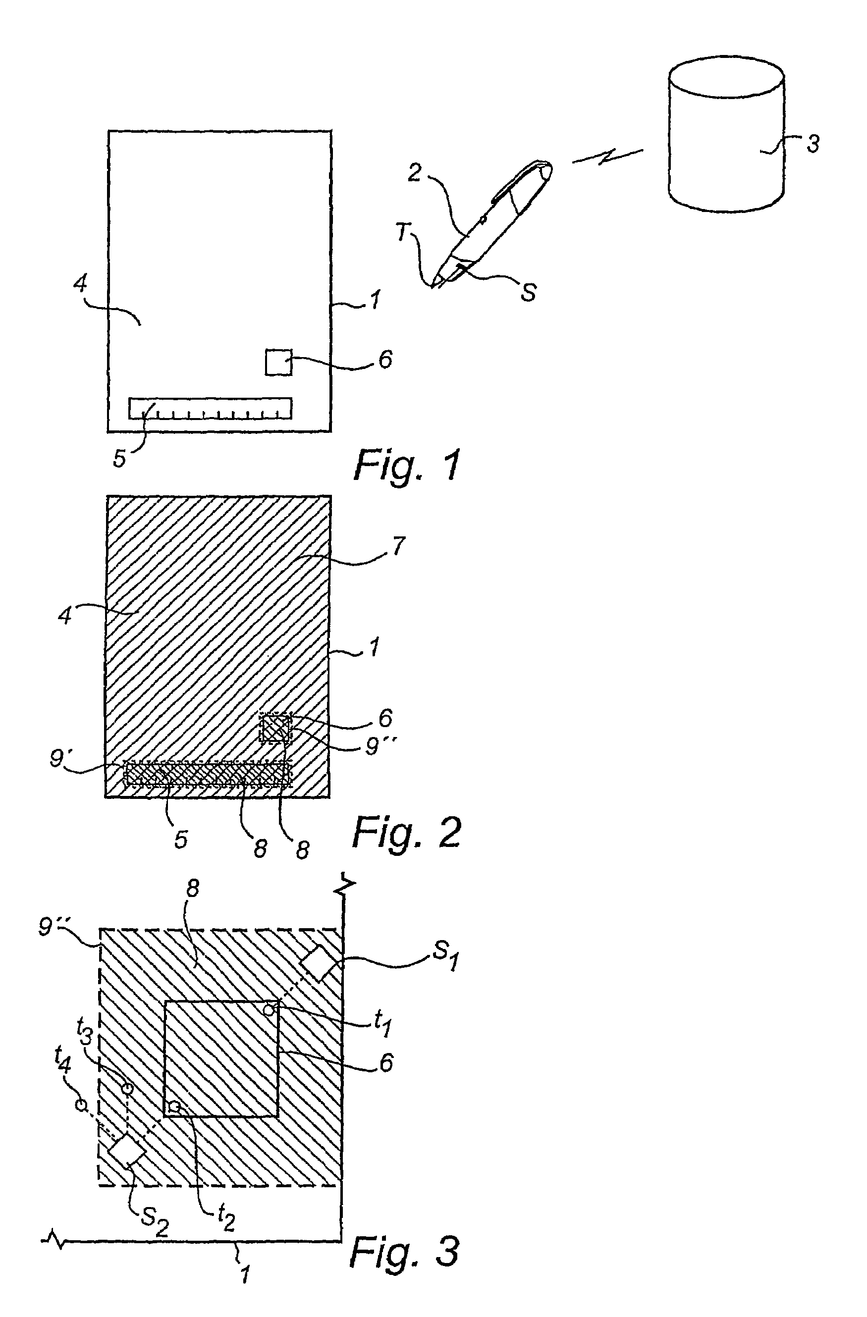
[0052]FIG. 1 shows schematically a system for information management in which the present invention can be used. The system comprises a base 1 in the form of a sheet of paper, a user unit 2 and an external unit 3. The paper 1 is provided with a position-coding pattern (not shown in FIG. 1). The user unit 2 is used to write on the paper 1 using a pen point T and to simultaneously record the pen strokes in digital form by means of a sensor S which images the position-coding pattern on the paper 1. The digitally recorded information can be processed in the user unit 2 and / or the external unit 3, to which it can be sent automatically or at a signal from the user.

[0053]The paper 1 shown in FIG. 1 is an example of a form which can be used for graphic e-mail messages. It has three different fields 4-6, a first field 4 constituting a message field, a second field 5 constituting an address field and a third field 6 constituting a send box. The different fields are marked on the paper in a wa...


PUM


Abstract

A product is on a surface provided with a first position code which codes coordinates for a plurality of first points. In at least one partial area on the surface, the product is further provided with a second position code which codes coordinates for a plurality of second points. The partial area further comprises a field which is associated with a predetermined function to be performed in consequence of a user unit being placed in the field. Methods and devices for coding and for recording of information from a surface are also described.

Description

CROSS-REFERENCE TO RELATED APPLICATIONS[0001]The present application claims the benefit of Swedish patent application No. 0201846-3, filed on 18 Jun. 2002 and U.S. Provisional patent application No. 60 / 391,922, filed on 28 Jun. 2002, which both are hereby incorporated by reference.[0002]Methods, apparatuses, products and computer programs relating to the same technical field as the present application are furthermore disclosed in U.S. provisional patent application No. 60 / 323,694, filed on 21 Sep. 2001 and subject to an obligation of assignment to the assignee of the present application.FIELD OF THE INVENTION[0003]The present invention relates to a product which on a surface is provided with a first position code which codes coordinates for a plurality of first points.[0004]The invention also relates to a method for coding, a coding device and a method and a device for recording information from a surface.BACKGROUND OF THE INVENTION[0005]It is already known that it is possible to di...

Claims


Application Information

Patent Timeline
Patent Type & Authority Patents(United States)
IPC IPC(8): G06K19/06G06F3/03G06F3/0354
CPCG06F3/0317G06F3/03545G06K19/06037G06F3/0321
Inventor BRYBORN, MATTIAS
Owner ANOTO IP LIC
Why Eureka
Try Eureka