Portable utility carrier apparatus

a utility carrier and portable technology, applied in the direction of carriers/perambulators with multiple axes, folding cycles, manufacturing tools, etc., can solve the problems of difficult loading and unloading of heavy cargo, and the inability to directly connect heavy cargo to the hitch, and achieve the effect of convenient movemen

Inactive Publication Date: 2007-07-31
GO PROD
View PDF17 Cites 90 Cited by
  • Summary
  • Abstract
  • Description
  • Claims
  • Application Information

AI Technical Summary

Benefits of technology

[0004]The portable utility carrier apparatus of the present invention consists of a raisable and lowerable platform that may house a variety of cargo. The platform is connected to a lift system that is used to raise and lower the platform. The apparatus is carried and transported solely via a receiver type hitch assembly one part of which is integral with the lift system and one part of which is conventionally mountable on a tran

Problems solved by technology

Pickup trucks and sports utility vehicles (SUVs) are designed to carry cargo, but for heavier items and containers, loading and unloading the cargo becomes problema

Method used


Image

  • Portable utility carrier apparatus
  • Portable utility carrier apparatus
  • Portable utility carrier apparatus

Examples


second embodiment

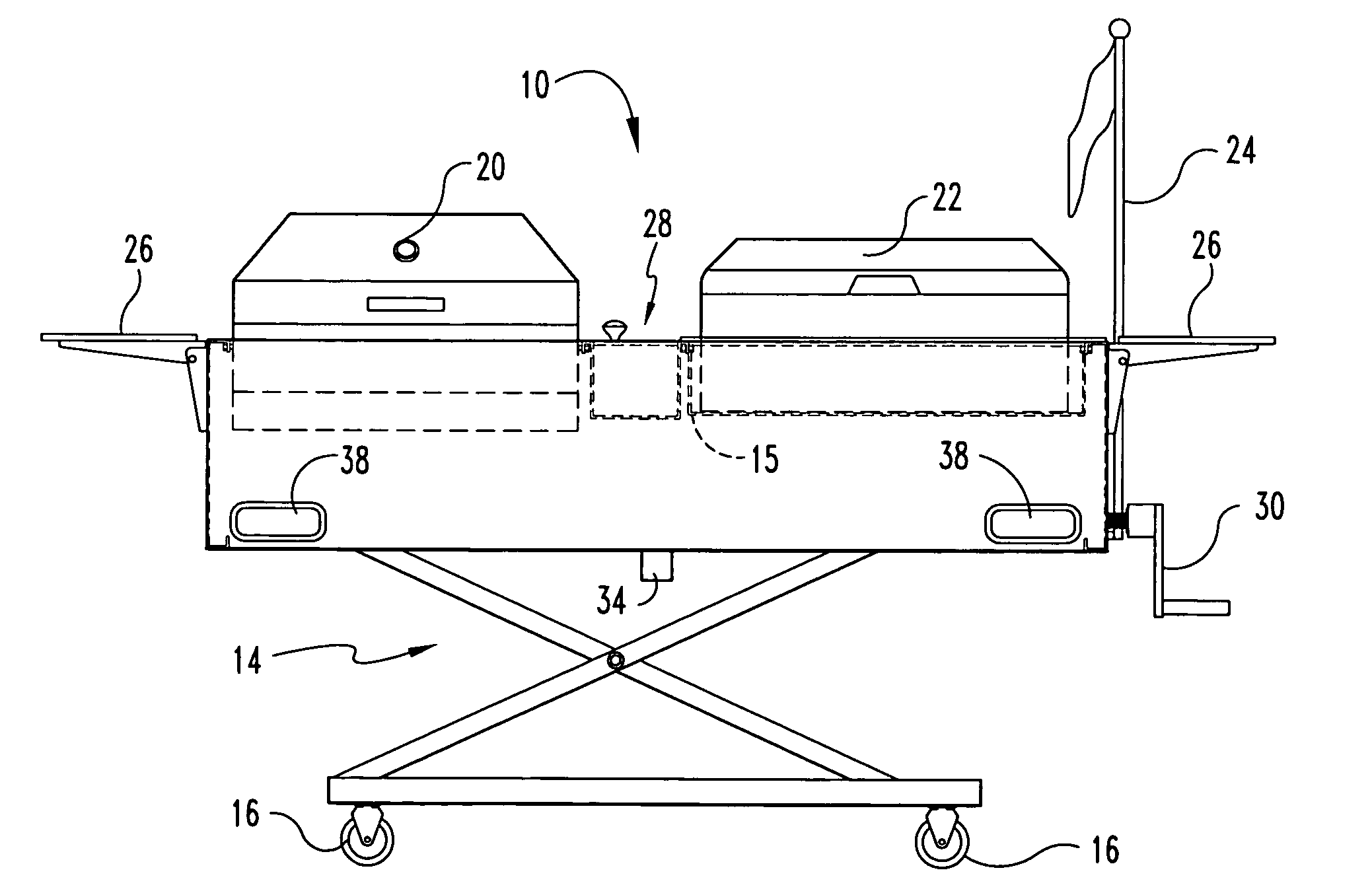
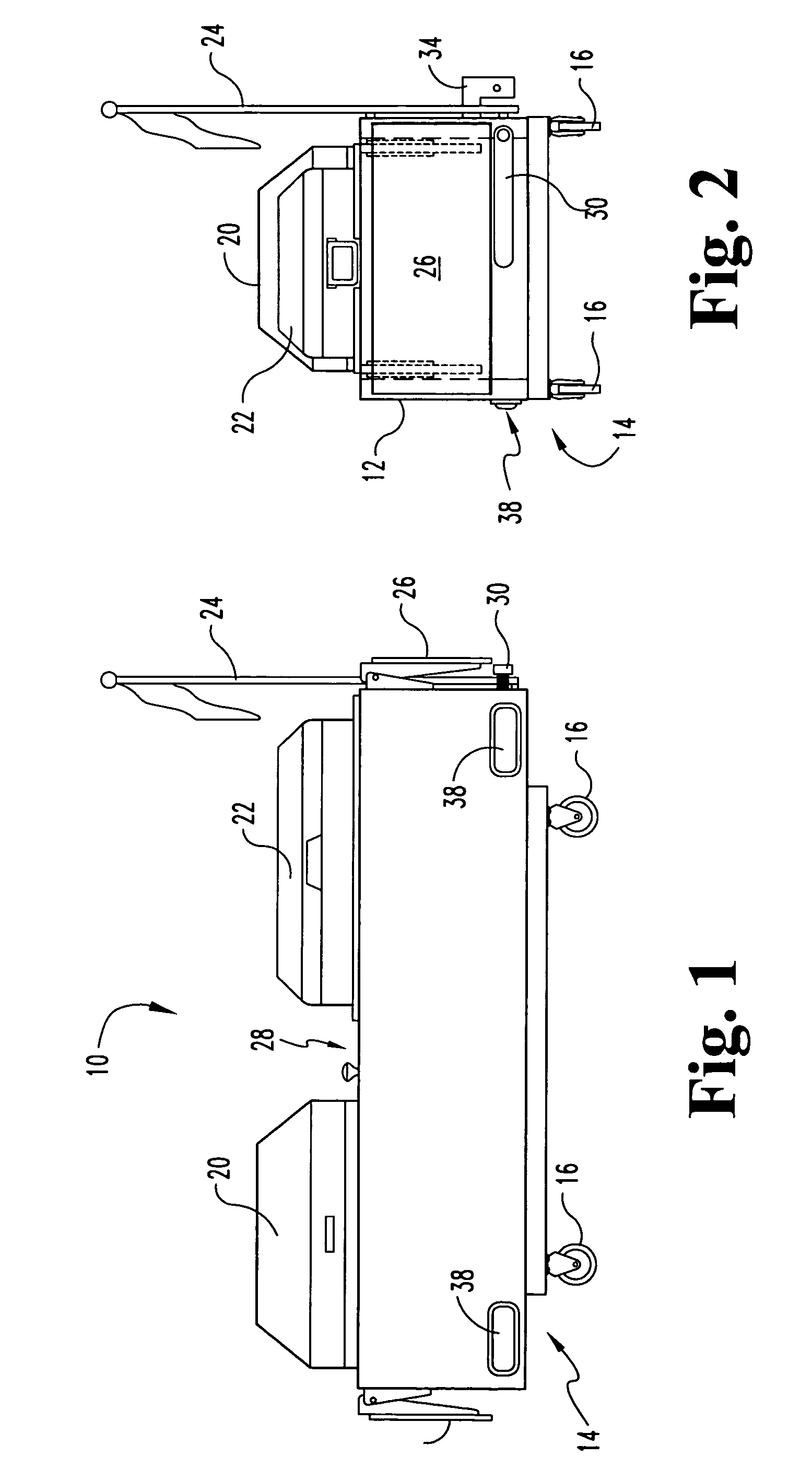
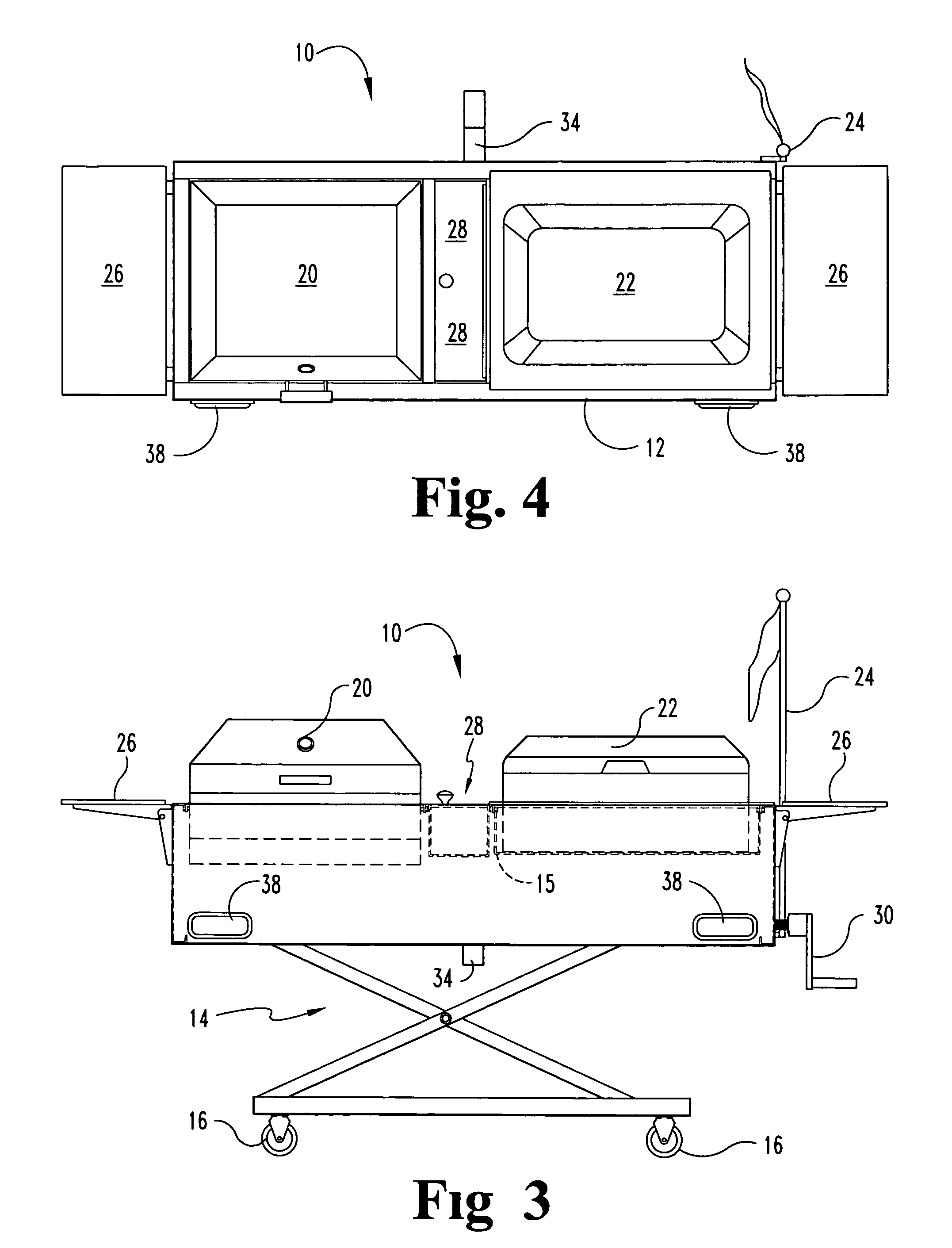
[0042]FIGS. 7-8 illustrate the present invention, a portable grilling apparatus 110 having a recessed housing platform 112 having at least one recess 126 formed therein for accepting a barbeque grill 120. A wheeled base 111 is connected to the portable grilling apparatus 110, and a lift system 114 is interposed between the base 111 and the recessed platform 112 for moving the wheeled base 111 relative to the platform 110 between a transport position and a use position.

[0043]The at least one recess 126 is sized to receive a barbeque grill 120, and may therefore have any shape convenient to accepting a particular barbeque grill, such as rounded or semispherical, or a rectangular parallelepiped.

[0044]The wheeled base 111 is preferably a rectangular frame 115 from which wheels 116 downwardly extend. The wheels 116 are preferably caster or pneumatic type, but may alternately be of any type convenient to transporting the portable grill 110 over short distances on relatively flat terrain.

first embodiment

[0045]The lift system 114 extends between the wheeled base 111 and the housing 112, and connects to each. In this embodiment, the lift system 111 includes a scissors-type lifting apparatus similar to that of the first embodiment above that may be cranked to alternately extend or diminish the distance between the housing 112 and the base 111. In other contemplated embodiments, the lift system may be of any convenient mechanical or electromechanical type, such as a worm drive, a pneumatic or hydraulic lifting assembly, an electric motor drive assembly, or the like.

[0046]The portable grilling apparatus 110 is attachable / detachable to a transport vehicle by using the scissors lift system 114. The scissors lift system 114 is raised until the square hitch tube 34 is above the height of the rollered receiver hitch 36 when mounted and pinned 37 and locked 39 to a transport vehicle (see FIGS. 5A-B). The apparatus 110 is then rolled on wheels 116 into place such that the square hitch tube 34 ...


PUM


Abstract

A transportable utility carrier apparatus for coupling to a transport vehicle, including an upper frame, a recessed platform connected to the upper frame, a wheeled base, a lift system interposed between the base and the upper frame for moving the wheeled base relative to the platform between a transport position and a freestanding position, a square hitch tube connected to the upper frame, and a rollered receiver hitch mountable to the transport vehicle. The wheels are spaced from the ground in the transport position. The square hitch tube is receivable within the rollered receiver hitch and the rollered receiver hitch eases insertion of the square hitch tube thereinto to prevent binding on unleveled ground.

Description

REFERENCE TO RELATED APPLICATION[0001]This application claims the benefit of co-pending U.S. patent application Ser. No. 09 / 976,623, filed Oct. 12, 2001 and claiming the benefit of U.S. Provisional Patent Application Ser. No. 60 / 240,430, filed Oct. 13, 2000, and co-pending U.S. patent application Ser. No. 10 / 410,900, filed Apr. 10, 2003 and claiming the benefit of U.S. Provisional Patent Application Ser. No. 60 / 373,062, filed Apr. 16, 2002.BACKGROUND OF THE INVENTION[0002]Pickup trucks and sports utility vehicles (SUVs) are designed to carry cargo, but for heavier items and containers, loading and unloading the cargo becomes problematic due to its weight and bulk. Further, while many trucks and SUVs are equipped with hitching connections, the heavy cargo cannot be directly connected to the hitch.[0003]There is therefore a need for a cargo container system that may be transported by a hitch equipped vehicle that does not need to be lifted into the vehicle. The present invention addre...

Claims


Application Information

Patent Timeline
IPC IPC(8): B62B3/02
CPCA47J37/0704A61G13/0018B25H1/04B25H3/02B60R11/06B62B3/02B66F7/0625B66F7/065A47J2037/0777A61G3/0209A61G13/105A61G2210/30B60R2011/004B62B2206/06
Inventor BRENNAN, DANIEL A.DRONEN, MARK A.
Owner GO PROD
Why Eureka
Try Eureka