Optical transmission system

a transmission system and optical technology, applied in optical transmission, transmission monitoring, electromagnetic transmission, etc., can solve the problems of osc signal error, osc error, long haul, etc., and achieve the effect of improving the signal control mechanism and preventing osc signal error

Inactive Publication Date: 2007-07-31
FUJITSU LTD
View PDF4 Cites 13 Cited by
  • Summary
  • Abstract
  • Description
  • Claims
  • Application Information

AI Technical Summary

Benefits of technology

[0015]In view of the foregoing, it is an object of the present invention to provide a more reliable optical transmission system with an improved signal control mechanism that avoids abrupt power variations of transmitted light beams, thereby preventing OSC signal errors from happening.

Problems solved by technology

Such systems have to make optical signals propagate over a distance of as much as 250 km, and an even longer haul is required in some of them.
(1) OSC Errors Caused by Amplifier Start-Up
In that transient period, a sudden increase in the optical amplifier power produces an abrupt Raman gain variation, and the consequent change in the OSC signal level could be too large for an OSC circuit at the receiving end to follow, thus resulting in an OSC signal error.
Similar to the above problem (1), a sudden start-up of a downstream Raman pump light source causes an abrupt Raman gain variation, and the resulting change in the OSC signal level could be too large for the OSC receiver to follow, ending up with an OSC signal error.
(3) Lack of Stability in Recovery from APSD
When the system tries to recover from shutdown, an OSC error could happen in a transient period of that process just because of the reasons described in (1) and (2).
This OSC error triggers the APSD mechanism, and the system should follow the same process again and again.

Method used


Image

  • Optical transmission system
  • Optical transmission system
  • Optical transmission system

Examples


Embodiment Construction

[0039]Preferred embodiments of the present invention will be described below with reference to the accompanying drawings, wherein like reference numerals refer to like elements throughout.

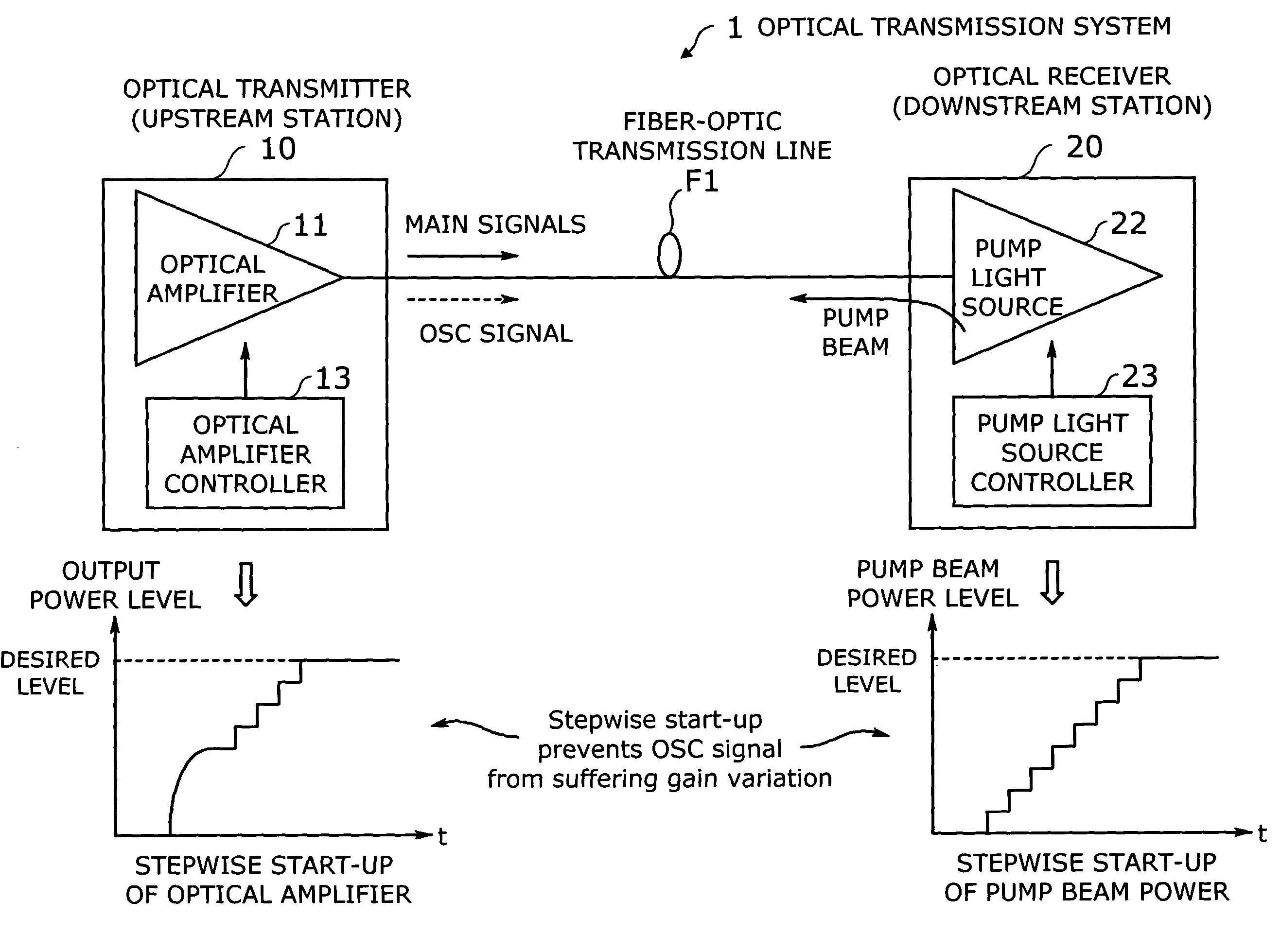
[0040]FIG. 1 is a conceptual view of an optical transmission system 1 according to the present invention. This system 1 is a long-haul repeaterless optical transmission system where an optical transmitter (or upstream station) 10 sends WDM optical signals to a remotely located optical receiver (or downstream station) 20 over a fiber-optic transmission line F1. While only one direction is illustrated in FIG. 1, the two end stations actually have both transmission and reception capabilities, so that the system 1 can transport signals in either direction. In other words, the illustrated elements and functions of the present invention can be integrated in a single device or a single station.

[0041]The optical transmitter 10 has an optical amplifier 11 and an optical amplifier controller 13. The optical ...


PUM


Abstract

A reliable optical transmission system with an improved signal control mechanism that avoids abrupt power variations of light beams, thereby preventing optical supervisory channel (OSC) signals from experiencing errors. An optical amplifier amplifies main signals under the control of an optical amplifier controller, which spends a first predetermined time to raise the output power of the optical amplifier up to a desired level. A pump light source produces a pump beam for injection to a fiber-optic transmission line so as to make it serve as an amplifying medium. The pump light source is controlled by a pump light source controller that spends a second predetermined time to raise the pump beam to a desired power level. This stepwise start-up process of the amplifier power and pump beam power prevents OSC signals from experiencing abrupt power variations.

Description

BACKGROUND OF THE INVENTION[0001]1. Field of the Invention[0002]The present invention relates to an optical transmission system, and more particularly to an optical transmission system which transports optical signals over a long distance.[0003]2. Description of the Related Art[0004]As a core component of today's information and communication infrastructures, optical network systems are expected to provide more sophisticated services in wider geographical areas. Rapid technology developments have thus been made in this field to meet the future needs in advanced information-age societies. Of particular interest in recent years is repeaterless optical transmission systems. While transoceanic undersea cable systems require intermediary repeaters to compensate for their fiber-optic cable losses, repeaterless optical transmission techniques can be used in other long-haul applications such as continent-to-island or island-to-island communications systems. There is an increasing demand for...

Claims


Application Information

Patent Timeline
Patent Type & Authority Patents(United States)
IPC IPC(8): H04B10/17H04B17/00H01S3/30H04B10/035H04B10/07H04B10/077H04B10/079H04B10/2537H04B10/294H04B10/297
CPCH04B10/0775H04B10/2916H04B10/2937H01S3/302H04B2210/08H04B2210/078
Inventor OHTANI, TOSHIHIROTAKAHASHI, TSUKASAISHIKAWA, EIJIIKEDA, HIROTODEGUCHI, HIROYUKI
Owner FUJITSU LTD
Why Eureka
Try Eureka