
Bi-stable hinge and systems using same

a technology of bi-stable hinges and hinges, applied in the field of mobile stations, can solve the problems of increasing the number of potentially damaging environments of mobile stations, increasing the mobility of mobile stations, and exposing them to an ever-increasing number of potentially damaging environments, so as to reduce the stress on various internal elements, reduce the effect of hinge assembly and cost-effective manufacturing products

Active Publication Date: 2007-07-31
NOKIA TECHNOLOGLES OY
View PDF5 Cites 42 Cited by
  • Summary
  • Abstract
  • Description
  • Claims
  • Application Information

AI Technical Summary

Benefits of technology

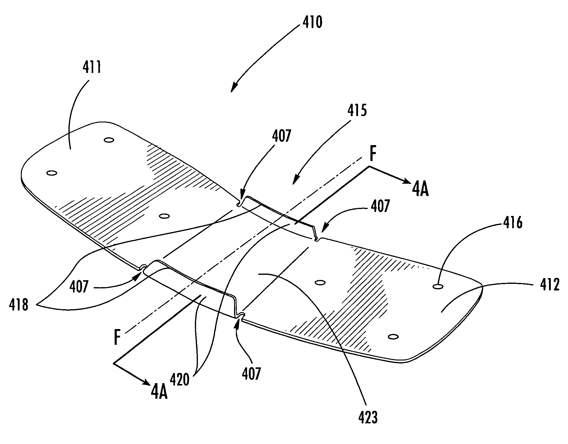
[0013]The present invention provides an improved hinge design for a mobile station, such as a mobile phone or other foldable electronic device, that simplifies hinge assembly and thus, provides a more cost-effective manufactured product. Moreover, the improved hinge design complements the aesthetic appeal of the foldable mobile station and results in less applied stress on various internal elements. Mobile stations and other foldable electronic devices include first and second functional components that are pivotally coupled together. In several embodiments of the present invention, the first and second functional components are mechanically coupled in foldable relation by a bi-stable member. The bi-stable member functions to bias the mobile station into a folded position and an open position.
[0015]In one embodiment, the bi-stable member comprises a laminate structure having a resilient substrate layer comprised of a polymer laminate, a strip of mesh or spring metal, a fiber reinforced composite or some combination thereof, that is biased toward the open position. The laminate structure further includes a plastically deformable layer configured to oppose the bias of the resilient substrate layer in the folded position. Accordingly, the folded position and the open position are reversible and stable positions.

Problems solved by technology

Early mobile station designs were necessarily large and bulky.
The radio communications equipment and battery units necessary for their operation generally were carried in one oversized unit; although in at least one early and cumbersome design the unit was actually divided into two pieces which were then connected by a power cable.
Unfortunately, several drawbacks have followed this new fashionability and convenience.
For example, the increased mobility of today's mobile stations has the unintended drawback of subjecting these mobile stations to an ever-increasing number of potentially damaging environments.
Accordingly, mobile stations are highly susceptible to damage.
To make matters worse, market forces continue to drive mobile stations smaller, therefore, making it more difficult to add bulky structural reinforcements that might protect the mobile stations.
This risk of damage is exacerbated by the number of externally accessible components that are provided on modern mobile stations.
Initially, such displays were limited to small, light emitting diodes (LEDs) that indicated whether the mobile station was “on” or, regarding mobile phones, whether a call was in progress.
They are, therefore, easily susceptible to damage by even a relatively minor impact.
Despite the hard, transparent cover or similar protective device, generally added to limit this vulnerability, LCDs remain one of the most easily damaged components in modern mobile stations.
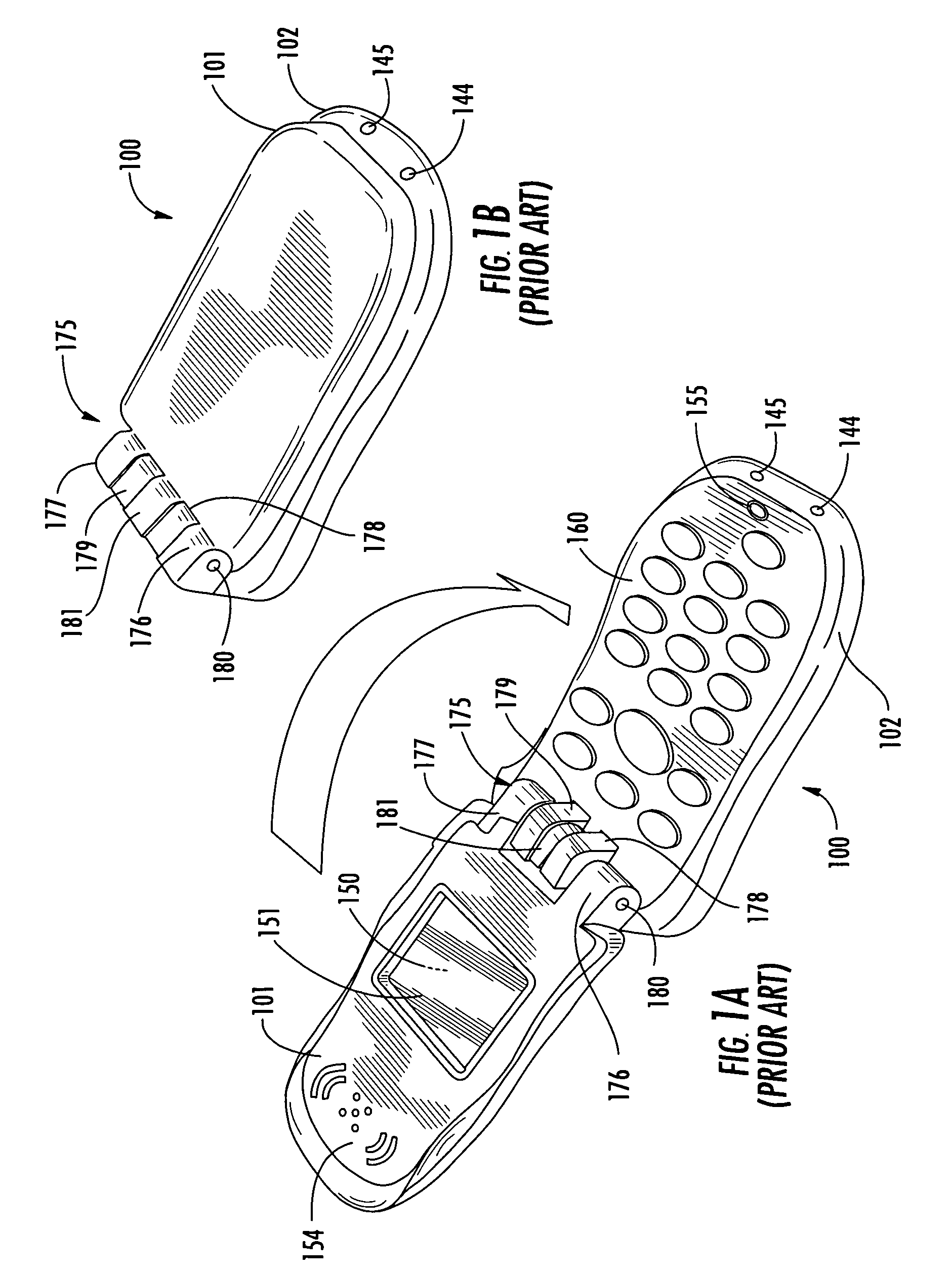
Despite the above improvements, the conventional folding mobile station design depicted in FIGS. 1A and 1B is still not optimal.
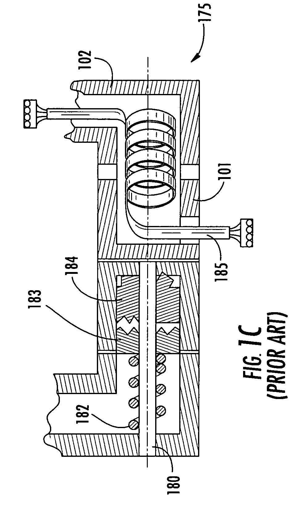
As illustrated in FIG. 1C, this hinge assembly 175 is relatively complex and more importantly, requires highly labor-intensive assembly operations and thus, is costly to manufacture.
As will be apparent to one of ordinary skill in the art, the complexity of the above hinge design results in cost-prohibitive and bulky hinge assemblies.
For example, the above hinge assembly requires precision elements, high part counts, and relatively long assembly times that all add to the manufactured cost.
In addition, the complex prior art hinge designs hinder the ability of designers to make stylish modifications.

Method used


Image

  • Bi-stable hinge and systems using same
  • Bi-stable hinge and systems using same
  • Bi-stable hinge and systems using same

Examples


Embodiment Construction

[0031]The present inventions now will be described more fully hereinafter with reference to the accompanying drawings, in which some, but not all embodiments of the invention are shown. Indeed, these inventions may be embodied in many different forms and should not be construed as limited to the embodiments set forth herein; rather, these embodiments are provided so that this disclosure will satisfy applicable legal requirements. Like numbers refer to like elements throughout.

[0032]The mobile station of the present invention uses bi-stable structures. These bi-stable structures comprise one or more extendable, coilable, members that can be advanced from a coiled or retracted state to an extended state. The simplest of the conventional bi-stable structures is the common steel tape measure. Advantageously, as is apparent in view of a tape measure, bi-stable structures may be advanced and recoiled from one state to the other and back a plurality of times. Suitable structures are disclo...


PUM

PropertyMeasurementUnit
Angleaaaaaaaaaa
Angleaaaaaaaaaa
Angleaaaaaaaaaa

Abstract

The present invention provides an improved hinge design for a mobile station or other electronic device that simplifies hinge assembly and thus, provides a more cost-effective manufactured product. Moreover, the improved hinge assembly complements the aesthetic appeal of the foldable mobile station and provides less stress on various internal elements. In particular, the present invention includes a foldable mobile station or other foldable electronic device having a first functional component that is coupled to a second functional component via a bi-stable structure. The bi-stable structure functions to bias the first and second functional components in either an open or closed position.

Description

CROSS-REFERENCES TO RELATED APPLICATIONS[0001]This application claims the benefit of U.S. provisional patent application Ser. No. 60 / 463,488, filed Apr. 17, 2003, which is fully incorporated herein by reference.FIELD OF THE INVENTION[0002]The present invention relates generally to mobile-stations, and more specifically to a mobile station having a folded design encompassing a bi-stable member.BACKGROUND[0003]The manufacture and design of today's mobile stations (also known as mobile phones, PDAs, pagers, laptop computers and the like) is constantly evolving. Early mobile station designs were necessarily large and bulky. The radio communications equipment and battery units necessary for their operation generally were carried in one oversized unit; although in at least one early and cumbersome design the unit was actually divided into two pieces which were then connected by a power cable. Advances in integrated circuitry and electricity storage technology have enabled mobile station d...

Claims


Application Information

Patent Timeline
IPC IPC(8): H04M1/00B32B3/00B32B3/04B32B7/022B32B15/08B32B27/06E05D1/02E05D1/04E05D11/00E05D11/10E05F1/12H04M1/02
CPCB32B3/04B32B7/02B32B15/08B32B27/06H04M1/0216E05D1/02E05D1/04Y10T428/24479E05D11/1078E05F1/1284E05Y2900/538E05Y2900/606E05D11/0081B32B7/022E05Y2999/00H04B1/38B32B3/00B32B2457/00B32B2307/51
Inventor HOLTORF, JIMMCKAY, MICHAELSULLIVAN, ANNHENNEN, ALEXANDREGIESECKE, TONIA
Owner NOKIA TECHNOLOGLES OY
Learn More