Air assist fuel injector for a combustor

a fuel injector and air-assist technology, which is applied in the ignition of turbine/propulsion engines, engine starters, lighting and heating apparatus, etc., can solve the problems of insufficient pressure drop across the fuel injector tip to provide sufficient velocity, the stability of the flame stability may still be relatively sensitive in such a fuel injector, and the inability of conventional fuel injector systems to provide sufficient spray across the inner passage airflow, etc., to achieve the effect of maximizing stability and minimizing the amount of smoke production

Active Publication Date: 2007-08-07
RTX CORP
View PDF10 Cites 71 Cited by
  • Summary
  • Abstract
  • Description
  • Claims
  • Application Information

AI Technical Summary

Benefits of technology

[0010]Air passes around the fuel shroud to the air jets to provide a focused application of air directly onto the fuel spray from each of the main fuel jets to impart additional velocity to the fuel as it is flowing out of the fuel nozzle. The air jets provide an increased pressure drop across a swirler to mix with the fuel from the main fuel jets and increase the resulting fuel spray velocity to a level high enough to reach a prefilmer wall of the swirler even during snap deceleration.
[0011]Generally, the fuel jets and the air jets are arranged to: focus each air jet on a respective fuel jet; complement the air swirl of the swirler; provide initial interaction between air and fuel within a sheltered region to ensure effective momentum exchange; provide a sufficiently high momentum air jet to impart enough momentum to the fuel from the fuel jet to increase the fuel velocity and traverse the swirler inner passage; provide the air jet wide enough to overlap the fuel jet; and provide fuel nozzle external contours which are cleared away so that fuel does not attach to fuel nozzle surfaces and lose the momentum imparted by the air.
[0013]The present invention therefore provides a fuel injector system which minimizes the amount of smoke production while maximizing stability even under snap deceleration conditions.

Problems solved by technology

Although effective, flame stability in such a fuel injector may still be relatively sensitive during snap deceleration conditions.
Conventional fuel injector systems may not provide sufficient spray transport across an inner passage airflow to reach the prefilmer wall under snap deceleration conditions as droplet sizes may be too small for effective centrifuge action to take place in the space available.
Furthermore, there may be insufficient pressure drop across the fuel injector tip to provide sufficient velocity to traverse the inner passage at the fuel flow common to snap deceleration conditions.
Such conventional fuel nozzle systems may thus suffer a loss in flame stability during snap deceleration conditions.

Method used


Image

  • Air assist fuel injector for a combustor
  • Air assist fuel injector for a combustor
  • Air assist fuel injector for a combustor

Examples


Embodiment Construction

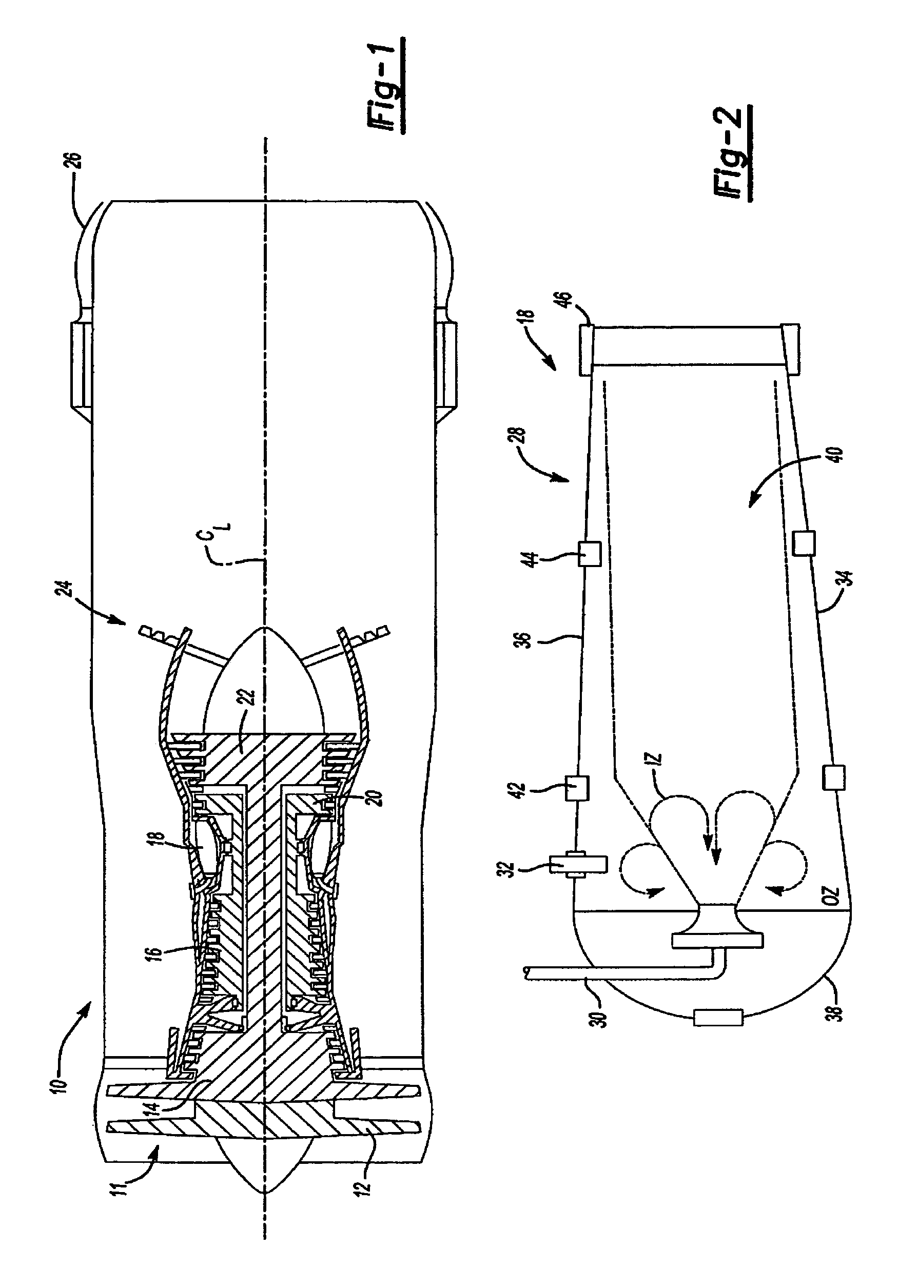
[0032]FIG. 1 illustrates a general cross-sectional view of a gas turbine engine 10. From an inlet 11, the major components of the engine 10 include a fan section 12, a low pressure axial compressor 14, a high pressure axial compressor 16, a burner section 18, a high pressure turbine 20, a low pressure turbine 22, an afterburner 24, and a nozzle 26.

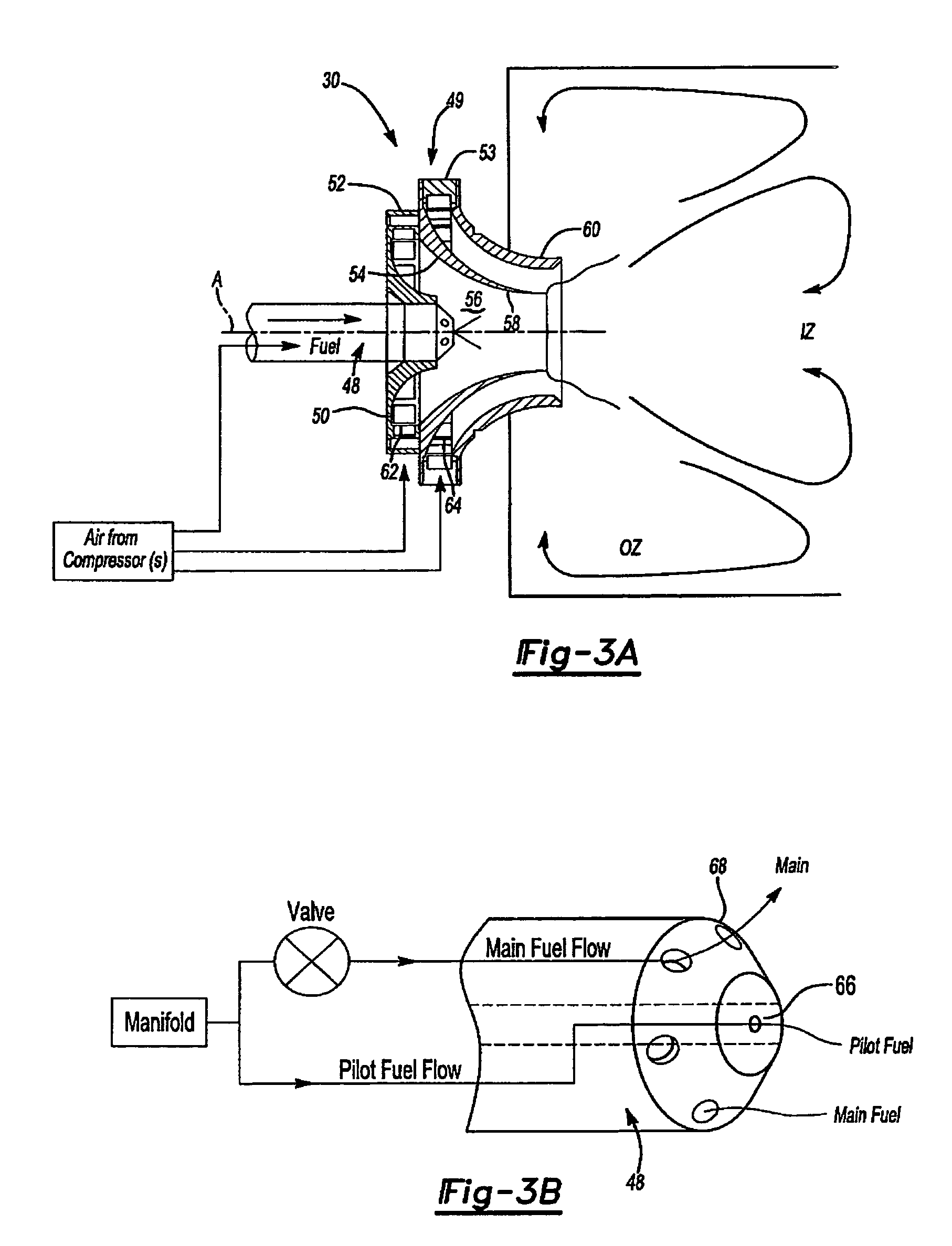
[0033]Referring to FIG. 2, a cross-sectional view of a portion of the burner section 18 includes an annular combustor 28, fuel injectors 30, and spark igniters 32. The igniters 32 light the fuel / air mixture provided to the combustor 28 from the fuel injectors 30 during engine start.

[0034]The annular combustor 28 includes an inner liner 34, an outer liner 36, and a dome 38 joining the inner liner 34 and the outer liner 36 at an upstream end. A cavity 40 formed between the inner liner 34 and the outer liner 36 defines a combustion chamber.

[0035]The fuel injectors 30 are preferably mounted to the dome 38. The fuel injectors 30 provide fuel an...


PUM


Abstract

A fuel injector system provides an air assist fuel nozzle which includes a fuel shroud and an air portion. Air passes around the fuel shroud to air jets in the air portion to provide a focused application of air directly onto a fuel spray from each of a multiple of main fuel jets to impart additional velocity to the fuel as it is flowing out of the fuel nozzle. The air jets increase the resulting fuel spray velocity to a level high enough to reach a prefilmer wall of a swirler even during snap deceleration conditions.

Description

[0001]This invention was made with government support under Contract No.: N0019-02-C-3003. The government therefore has certain rights in this invention.BACKGROUND OF THE INVENTION[0002]The present invention relates to a fuel / air mixer for a combustor and more particularly to a focused application of air directly on the fuel spray as it is flowing out of a fuel injector to increase the transport of fuel spray during engine snap deceleration conditions.[0003]One goal in the design of combustors, such as those used in gas turbine engines of high performance aircraft, is to minimize the amount of smoke produced by the combustion process in the gas turbine engine. For military aircraft in particular, smoke production creates a “signature” which may increase aircraft visibility.[0004]Another objective in the design of combustors for high performance aircraft is to maximize the “static stability” of a combustor. The term “static stability” refers to the ability to initiate the combustion ...

Claims


Application Information

Patent Timeline
Patent Type & Authority Patents(United States)
IPC IPC(8): F23R3/12F23R3/28F23D11/10
CPCF23D11/107F23D2900/11101
Inventor GRAVES, CHARLES B.DESALLE, STEPHANIE
Owner RTX CORP
Why Eureka
Try Eureka