Water-from-air system using desiccant wheel and exhaust

a technology of desiccant wheel and air system, which is applied in the direction of defrosting, separation process, domestic cooling apparatus, etc., can solve the problems of not being readily available, dangerous and costly

Inactive Publication Date: 2007-08-07
HAMILTON SUNDSTRAND CORP
View PDF10 Cites 42 Cited by
  • Summary
  • Abstract
  • Description
  • Claims
  • Application Information

AI Technical Summary

Problems solved by technology

There are many environments in which an engine is used where water is desired but not readily available.
For example, during military campaigns water is typically brought to remote or arid regions where water is not readily available.
Water must be brought along a supply line to troops, where military vehicles are often present, which is dangerous and costly.

Method used


Image

  • Water-from-air system using desiccant wheel and exhaust
  • Water-from-air system using desiccant wheel and exhaust
  • Water-from-air system using desiccant wheel and exhaust

Examples


Embodiment Construction

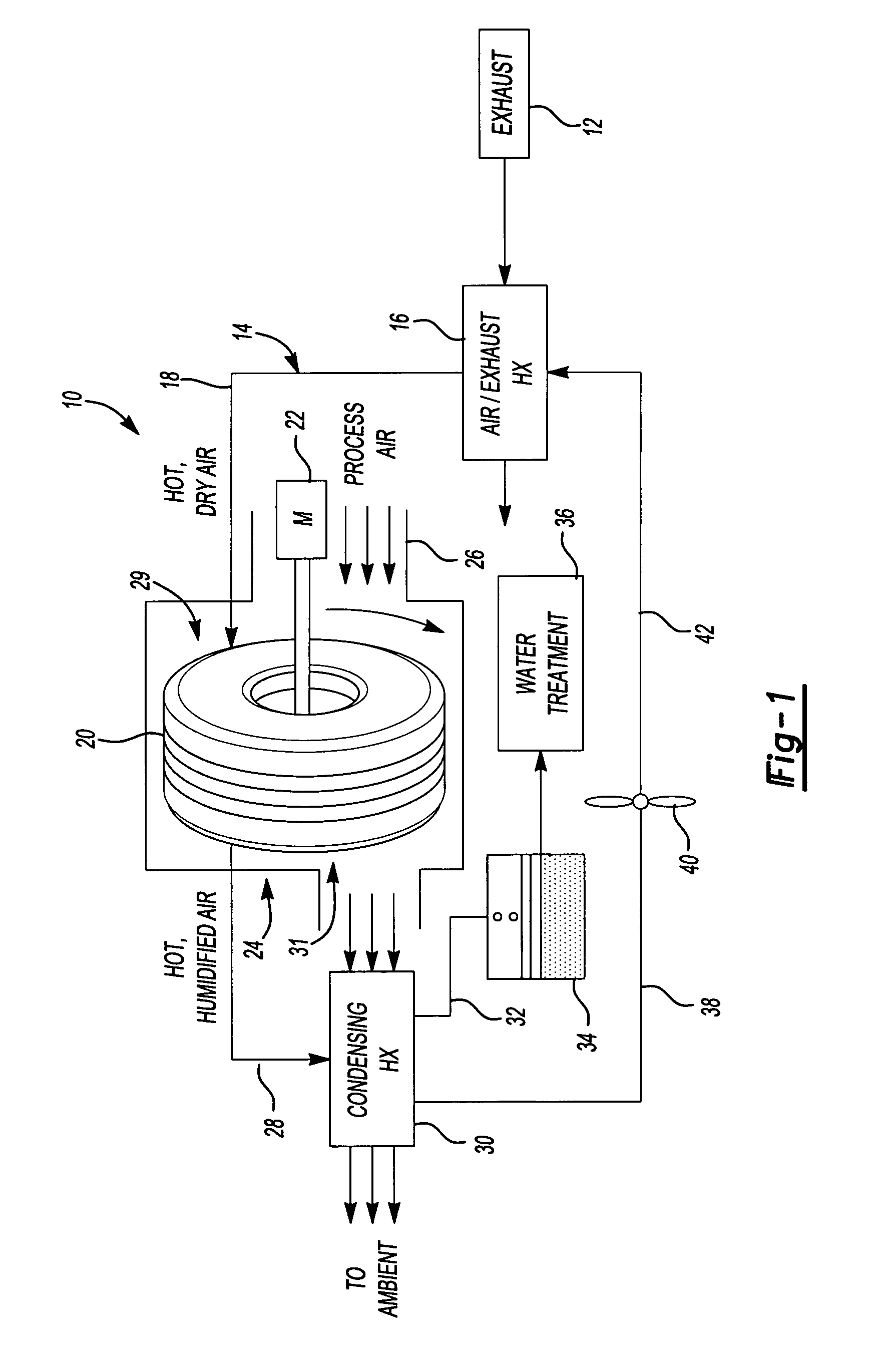
[0011]A water production unit 10 is schematically shown in FIG. 1. The unit 10 includes an heat source 12, such as the exhaust from a vehicle, that provides heat to an air loop 14. Specifically, a heat exchanger 16 is arranged relative to the air loop 14 to heat the air within the air loop 14 using vehicle exhaust. The unit 10 may be integrated with a mobile military vehicle, and the heat source 12 may be provided by a combustion engine that propels the vehicle. The heat source may also be provided by a stationary power plant or electrical heaters.

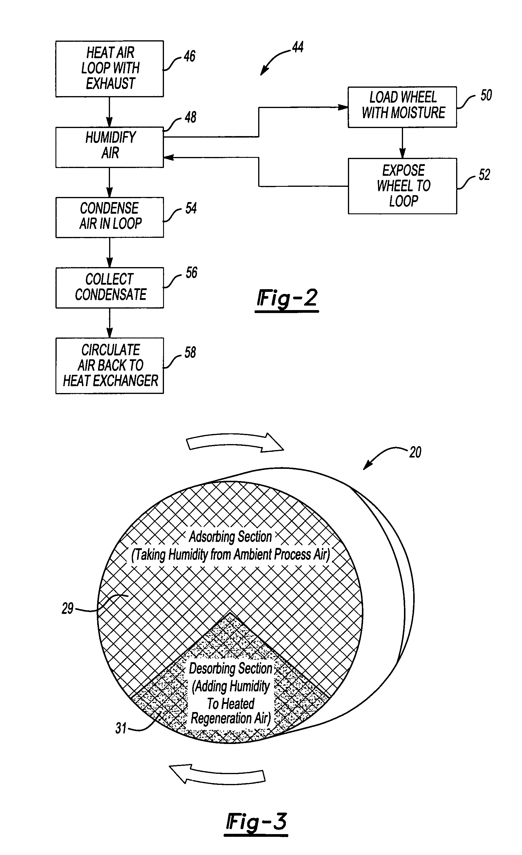
[0012]A first passage 18 provides a dry air passage arranged downstream and in fluid communication with the heat exchanger 16. A desiccant wheel 20 is arranged downstream and in fluid communication with the first passage 18 and upstream of a second passage 28 that provides a humidified air passage.

[0013]The desiccant wheel 20 is arranged in a housing 24 and is rotated slowly about an axis by a motor 22. A controller (not shown) may be conn...


PUM

PropertyMeasurementUnit
motive energyaaaaaaaaaa
temperatureaaaaaaaaaa
heataaaaaaaaaa

Abstract

A water production unit is provided that uses a desiccant wheel for extracting water from an air loop. A portion of the air loop is heated using exhaust from, for example, a vehicle to regenerate the desiccant wheel.

Description

[0001]The present application claims priority to U.S. Provisional Application Ser. No. 60 / 687,737, filed Jun. 6, 2005.BACKGROUND OF THE INVENTION[0002]This invention relates to a water production unit that uses engine exhaust heat or electrical power to provide the motive energy to recover water from ambient air.[0003]There are many environments in which an engine is used where water is desired but not readily available. For example, during military campaigns water is typically brought to remote or arid regions where water is not readily available. Water must be brought along a supply line to troops, where military vehicles are often present, which is dangerous and costly. One by-product of a combustion engine is waste heat in the form of high temperature exhaust. This waste heat can be used to drive a process to recover water from ambient air. Electrical power can be used when the engine is off and waste heat is not available.[0004]A water recovery system has been proposed to recov...

Claims


Application Information

Patent Timeline
Patent Type & Authority Patents(United States)
IPC IPC(8): F25D17/02
CPCB01D5/0027B01D53/06B01D53/261B01D53/265
Inventor TONGUE, STEPHEN
Owner HAMILTON SUNDSTRAND CORP
Why Eureka
Try Eureka