Membrane valve and second stage pressure reducer for two-stage underwater regulators incorporating said valve

Active Publication Date: 2007-08-07
SCUBAPRO EUROPE SRL
View PDF11 Cites 31 Cited by
  • Summary
  • Abstract
  • Description
  • Claims
  • Application Information

AI Technical Summary

Benefits of technology

[0013]An advantage of the present invention is to increase the operating performance of a membrane valve by decreasing the swelling deformation of the central portion of the shutter disk during the outflow of liquid or gas, thereby preventing the retention of liquid or gas under the shutter disk and facilitating the ejection of gas or liquid.
[0014]Another advantage of the present invention is to increase the operating performance of a membrane valve by forcing the shutter disk to open in book-like fashion during ejection of gas or liquid, thereby increasing the lift of the free peripheral edges of the shutter disk and the available passageways for the gas or liquid.
[0015]A further advantage of the present invention is the ability to fine-tune the operating performance of a membrane valve by varying the number, type and positions of the stop ribs and/or of the secondary clamp

Problems solved by technology

While the elongated shape increases the outflow area due to the longer perimeter of sealing lip 101, the two-pin design does not improve on the swelling problem encountered with circular membranes and with one-pin designs.
On the contrary, the p

Method used


Image

  • Membrane valve and second stage pressure reducer for two-stage underwater regulators incorporating said valve
  • Membrane valve and second stage pressure reducer for two-stage underwater regulators incorporating said valve
  • Membrane valve and second stage pressure reducer for two-stage underwater regulators incorporating said valve

Examples


first embodiment

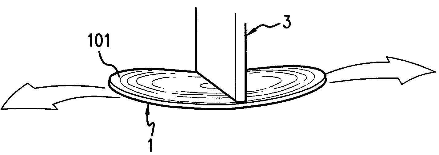
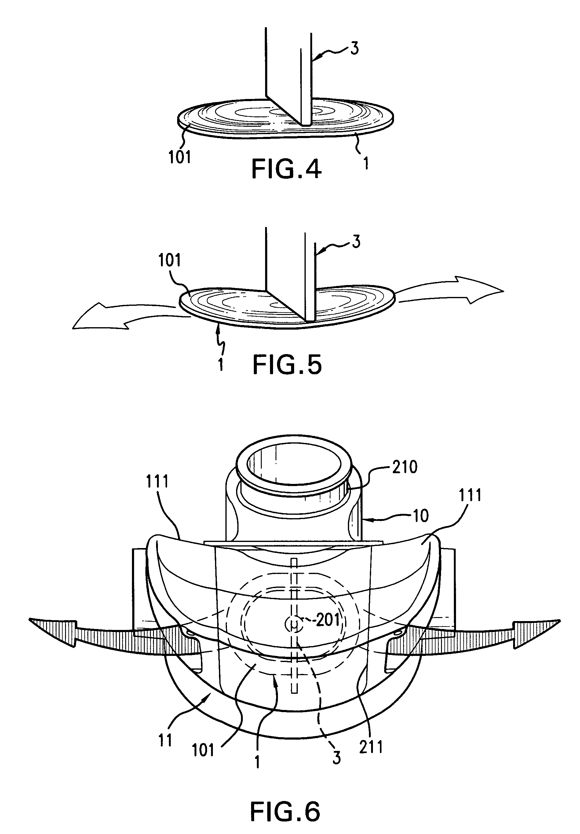
[0037]FIGS. 4 and 5 illustrate a membrane valve including the invention. A stop rib 3 is adjacent to a diameter of shutter disk 1, on the face opposite to valve seat 2, and controls the elastic deformation of shutter disk 1. Stop rib 3 is either in contact or in close proximity to shutter disk 1, and may or may not exercise pressure on shutter disk 1. Stop rib 3 may exhibit different forms, for instance, stop rib 3 may be blade-shaped with a peripheral edge 103 of square form, of tapered form, of beveled form, or of a rounded form. When peripheral edge 103 has a rounded form, engraving marks on shutter disk 1 are reduced or eliminated.

[0038]Because stop rib 3 either prevents or reduces the swelling deformation of shutter disk 1 under overpressure conditions, stop rib 3 forces shutter disk 1 to lift its peripheral portions as if shutter disk 1 were hinged along stop rib 3, thereby causing the membrane valve to open in a book-like fashion. Further, the book-like opening of shutter dis...

second embodiment

[0043]FIGS. 12A and 12B illustrate a perspective view and a plan view of the invention, wherein stop rib 3 is in discontinuous contact with shutter disk 1 because edge 103 has a toothed profile. Variations of this embodiment comprise edge 103 with a comb-like profile.

third embodiment

[0044]FIGS. 13A and 13B illustrate the invention, wherein the central portion of edge 103 has an extended profile in the area corresponding to primary clamping pin 201. Such extended profile includes protrusions 503 and 603 that first extend in divergent directions and then converge to disappear within the main body of stop rib 3. Protrusions 503 and 603 may exhibit either polygonal or curvilinear shapes, and may be positioned over the area of shutter disk 1 corresponding to clamping pin 201 or elsewhere. Variations of this embodiment comprise protrusions 503 and 603 that extend in divergent direction but do not converge to disappear within the main body of stop rib 3.

[0045]FIGS. 15A and 15B and 16A and 16B illustrate two variations of a fourth embodiment of the invention, wherein stop rib 3 consists of a row of rod-shaped members 33 spaced from each other. The number and dimensions of rod-shaped members 33 varies according to the construction particulars and to the desired operatin...


PUM


Abstract

A membrane valve wherein the shutter disk is retained in contact with the valve seat during ejection of liquid or gas by means of one or more ribs that are substantially in contact with the shutter disk along one or more lines secant to the shutter disk and/or by means of one or more rows of secondary clamping pins that are engaged in matching openings on the valve seat. Further, a second stage pressure reducer for two-stage underwater regulators incorporating a membrane valve wherein the shutter disk is retained in contact with the valve seat during exhalation of gas by means of one or more ribs that are substantially in contact with the shutter disk along one or more lines secant to the shutter disk and/or by means of one or more rows of secondary clamping pins that are engaged in matching openings on the valve seat.

Description

CROSS REFERENCE TO RELATED APPLICATIONS[0001]This patent application claims the priority of foreign patent application SV2003A000003, filed in Italy on Feb. 4, 2003 and titled “Valvola a membrana e secondo stadio di riduzione di pressione per erogatori bistadio per uso subacqueo provvisto di detta valvola.”BACKGROUND OF THE INVENTION[0002]Membrane valves are used in a variety of fields and more particularly in underwater breathing apparatus, for example to regulate air outflow in pressure regulators and water outflow in masks and snorkels.[0003]FIG. 1 illustrates a membrane valve according to the prior art, which comprises a shutter disk 1 of flexible material and a valve seat 2 with a continuous surface and one opening. Shutter disk 1 includes a cap of circular perimeter with a central portion that is essentially flat and further with a peripheral sealing lip 101, of essentially conical shape, that rests on annular wall 202 of valve seat 2. A primary clamping pin 201 extends from t...

Claims


Application Information

Patent Timeline
IPC IPC(8): F16K15/14A62B18/10
CPCF16K15/148Y10T137/7845Y10T137/7888Y10T137/784F16K15/1402
Inventor SEMEIA, ROBERTO
Owner SCUBAPRO EUROPE SRL
Why Eureka
Try Eureka