Candle with magnetically activated internal illumination

a magnetically activated, internal illumination technology, applied in the field of candles, can solve the problems of affecting the ability of candles to provide decoration and view, forming smoke during operation, and aluminum core, so as to avoid its combustion and achieve more attractiveness

Inactive Publication Date: 2007-08-07
SCHAWBEL
View PDF4 Cites 16 Cited by
  • Summary
  • Abstract
  • Description
  • Claims
  • Application Information

AI Technical Summary

Benefits of technology

[0016]The effective benefits with the scheme mentioned above are as follows. First, since the wick projects from the substantially opaque portion of the candle, the light show in the substantially light-transmissible portion is not washed out by or interfered with by the light of the flame of the wick. Further, because the electronic light emitting device is directly controlled by positioning the candle so that the magnet is moved into or out of proximity to the magnetic reed switch, there is no need for a light pipe or other such flame-sensing structure to be embedded in the candle body, and thus no ash residue is created that would spoil the decorative function of the candle. Moreover, it is also possible (although not required) to dispose the candle within a glass container which will introduce more attractiveness as more colorful light will be sent out, while at the same time containing the candle nicely. The use of a flame barrier between the bottom of the candle and the light emitting device prevents the light emitting device from catching fire; since the light emitting device is mostly made of plastic, avoiding its combustion is quite desirable.

Problems solved by technology

A major drawback is that the aluminum core here is made from two small aluminum foil bars with a layer of insulating material between them set parallel with the wick.
However, burnt ash will remain from the combustion of the insulating material and the melting of the aluminum, and this negatively affects the candle's ability to provide decoration and view.
Finally, as with ordinary candles, some kind of smoke can be formed during operation, especially if the wick burns all the way down to the LEDs.
This design and the one mentioned above suffer from a major deficiency.
The light show effect is thereby diminished by the very trigger mechanism that activates it (the flame), and the result is not very impressive.

Method used


Image

  • Candle with magnetically activated internal illumination
  • Candle with magnetically activated internal illumination
  • Candle with magnetically activated internal illumination

Examples


Embodiment Construction

[0025]The invention will be now be described with reference to the attached FIGS. 1-8. It should be noted that these figures are exemplary in nature and in no way serve to limit the scope of the invention, which is defined by the claims appearing hereinbelow and their reasonable equivalents.

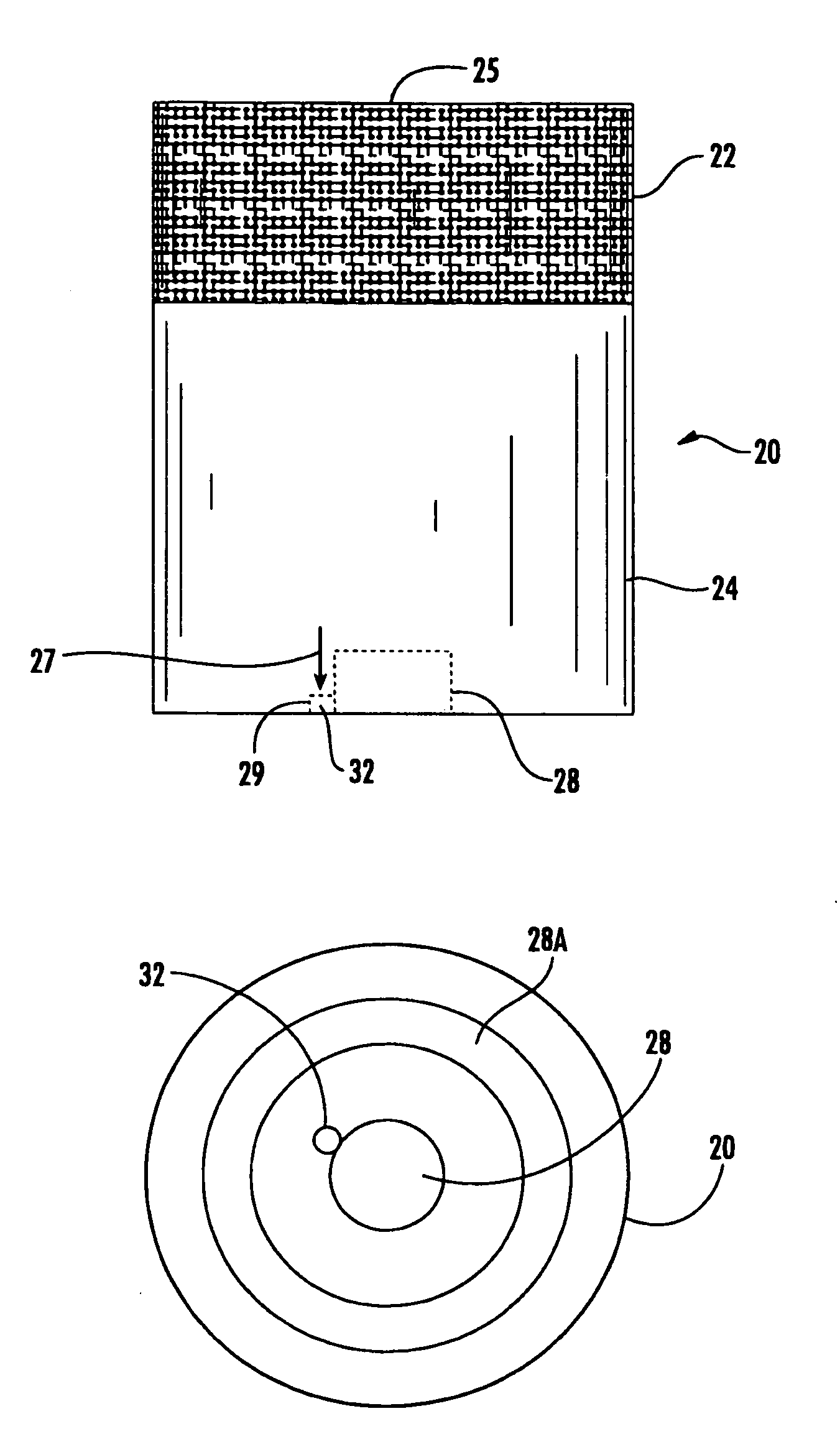
[0026]The basic components of the invention include candle base 10 and candle 20, which is placeable and relatively securable atop base 10. Candle 10 may be made from wax, paraffin, or any other material from which candles may be made or have been made.

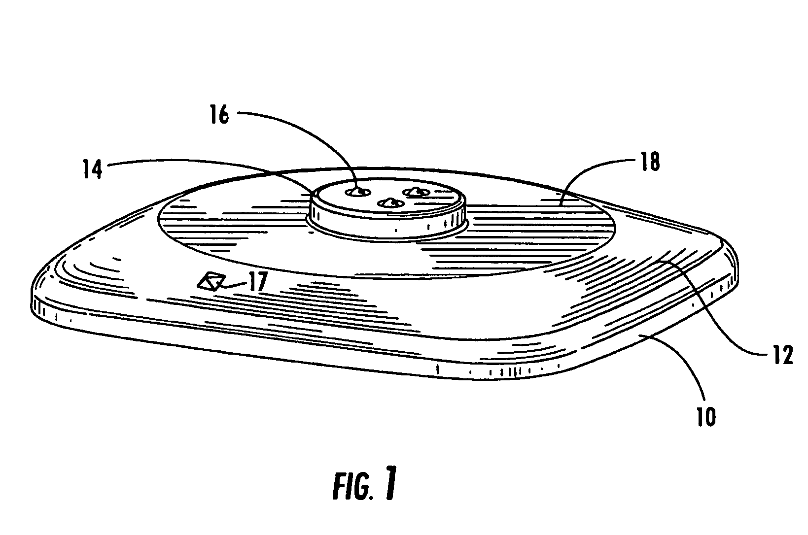
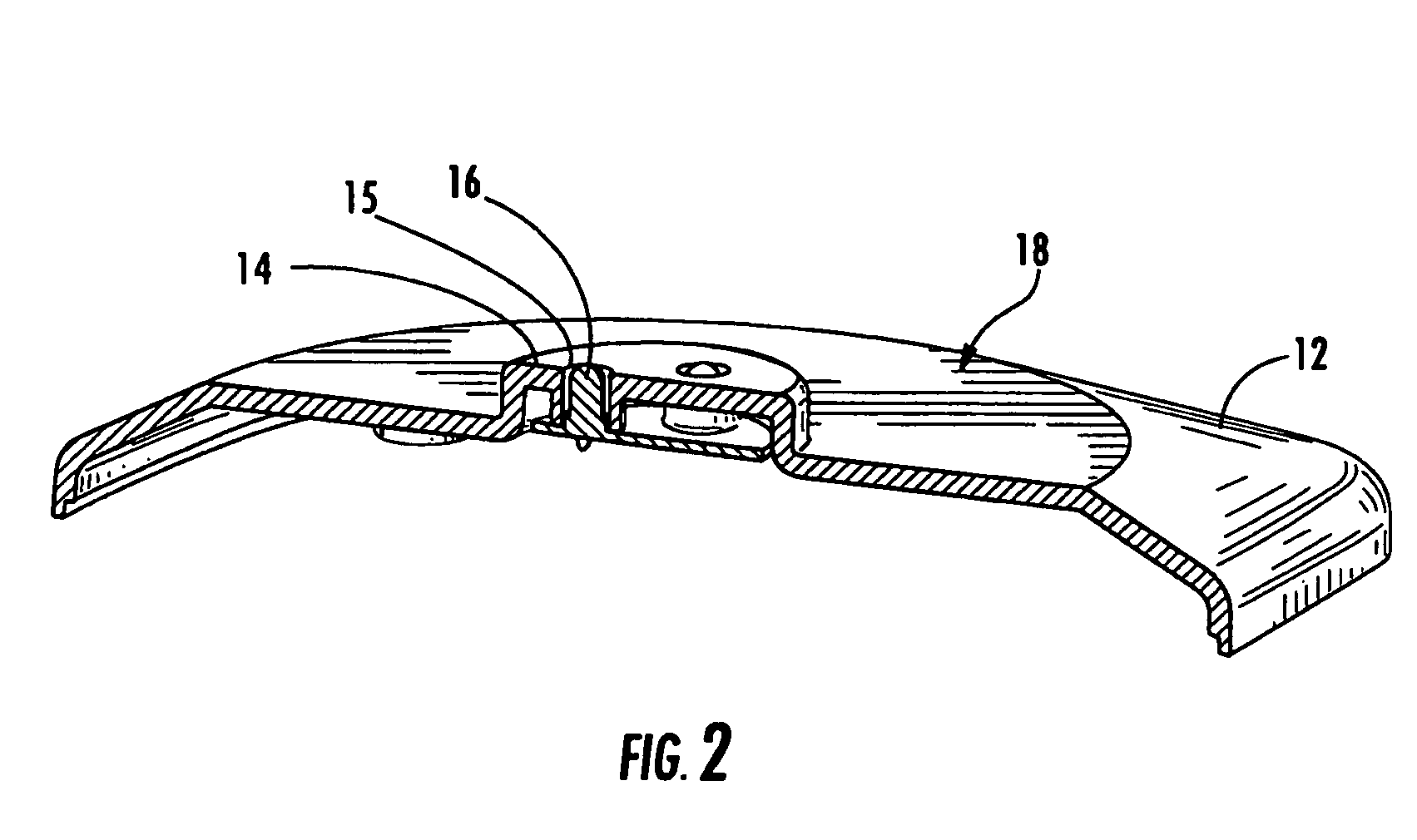
[0027]As best shown in FIGS. 1 and 2, base 10 includes a main base body 12 having a protrusion 14 projecting upward therefrom. In the embodiment shown, a light emitting device in the form of several LEDs 16 are recessed within protrusion 14; LEDs 16 may be positioned anywhere on or in protrusion 14 so long as at least a portion of each of the LEDs is not covered and able to shine light into a candle placed above it. Around or otherwise near protrus...


PUM


Abstract

A candle and base combination with a decorative light element is provided. The candle body preferably has a first substantially opaque section and a second at least partially translucent section, and at least one hollow portion formed in the second section. The base body has at least one protrusion fittable into the hollow portion. The wick projects from the first section of the candle body. A light emitting device is disposed in one of the base body or the main candle body in the second section, the light emitting device having associated therewith a magnetic switch closable in the presence of a magnetic field. A magnet is disposed in the other of the base body or the main candle body in the second section. When the main candle body is placed on the base body and the magnet is aligned with the magnetic switch, the light emitting device is activated.

Description

RELATED APPLICATIONS[0001]This is a Continuation-in-Part of U.S. patent application Ser. No. 10 / 926,525 filed Aug. 26, 2004, now U.S. Pat. No. 7,098,600 which claims priority from Chinese Patent Application No. 2003-20115105.9 filed Nov. 25, 2003.BACKGROUND[0002]1. Field of the Invention[0003]The invention relates to candles, and more specifically to decorative candles having an auxiliary decorative internal source of illumination.[0004]2. Description of the Related Art[0005]A candle usually emits light by the burning of its wick, however its use as a primary lighting instrument has been reduced with the popularization of electric light. Therefore, the candle is currently used more frequently as decoration.[0006]As a result of this trend, there have emerged a number of decorative and entertainment candle-related products, one example of which can be found in Chinese Patent No. 02233525.0. This patent teaches a candle-based product having a flashing function having a candle and a bas...

Claims


Application Information

Patent Timeline
Patent Type & Authority Patents(United States)
IPC IPC(8): F21V5/00F21SH05B39/04
CPCC11C5/008F21S19/00F21V23/0442Y10S362/81F21Y2113/02Y10S362/802F21Y2101/02F21Y2113/20F21Y2115/10
Inventor WANG, WEN DER
Owner SCHAWBEL
Why Eureka
Try Eureka