Crop processing device with relief system

a technology of processing device and relief system, which is applied in baling, agriculture, agricultural tools and machines, etc., can solve the problems of unavoidable plugging and too much crop entering the space, and achieve the effect of facilitating the control of the sheet and facilitating the movement of stress fr

Active Publication Date: 2007-08-07
DEERE & CO
View PDF18 Cites 32 Cited by
  • Summary
  • Abstract
  • Description
  • Claims
  • Application Information

AI Technical Summary

Benefits of technology

[0005]By means of this teaching the sheet will move a certain distance as soon as friction between the crop and the sheet increases. This allows the rotor to rotate further and possibly to overcome the high compression. However, since the throat does not open no more crop can enter the space. This is especially important in cases, in which the crop mat rolls on itself and could clog the throat area, if it is allowed to enter the space. The control may be set to allow a circumferential movement of such amount and direction, that immediate clogging is avoided. The rotor may be any revolving element (not only round and cylindrical) that repeatedly grasps and delivers crop or other material to be conveyed. The crop engaging elements may be teeth, tines, bars, etc. and may be used to cut, condition, or just convey the crop. The sheet may be of rigid construction or a sheet metal with certain flexibility. It may consist of a sheet of fixed length in the circumferential direction or of at least two parts overlapping each other. Overlapping sheet portions have as an advantage that no gap will occur, when one of the parts moves in the circumferential direction. Of course “circumferential” may also allow a limited radial movement towards or away from the rotor. The control may be a motor, a linK or any other device.
[0017]Due to the high capability to adjust to varying circumstances during the conveyance of crop, such a crop processing device is of very good use in a round or square baler, a self-loading wagon, a harvester, a combine or the like.

Problems solved by technology

However, since the throat does not open no more crop can enter the space.
In some cases too much crop may have entered the space between the sheet and the rotor and either plugging is unavoidable or the crop must be given more space, or the crop processing device has to be cleaned.

Method used


Image

  • Crop processing device with relief system
  • Crop processing device with relief system
  • Crop processing device with relief system

Examples


Embodiment Construction

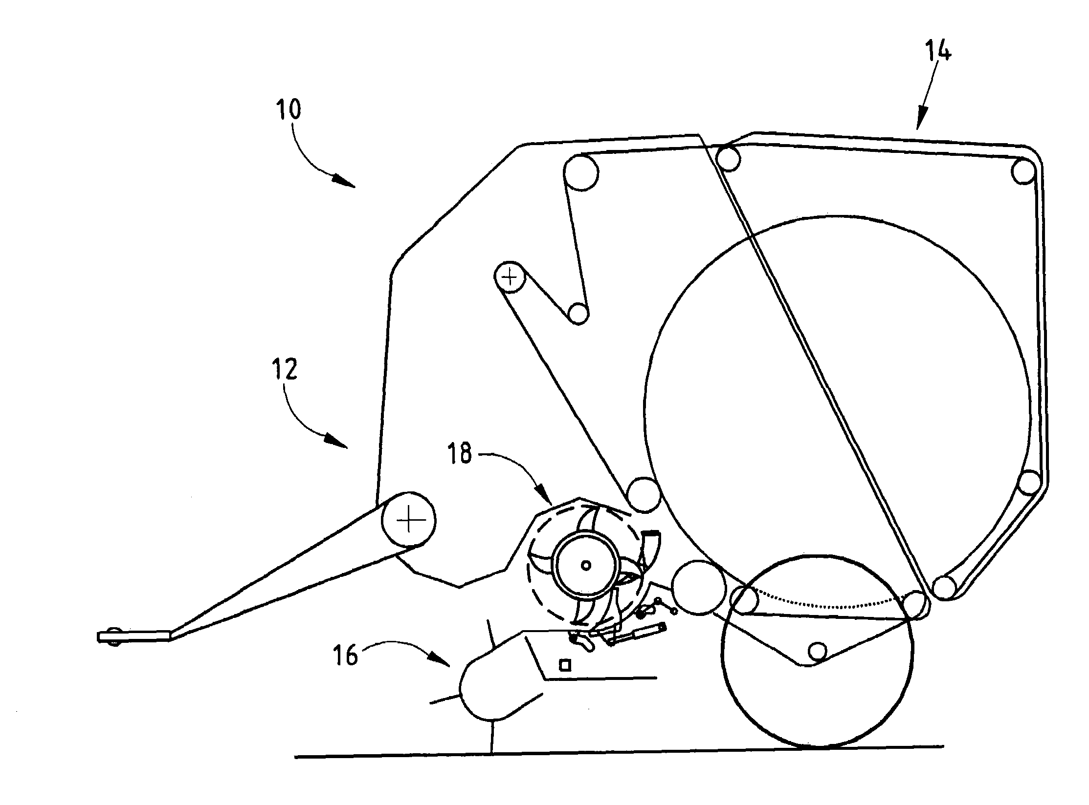
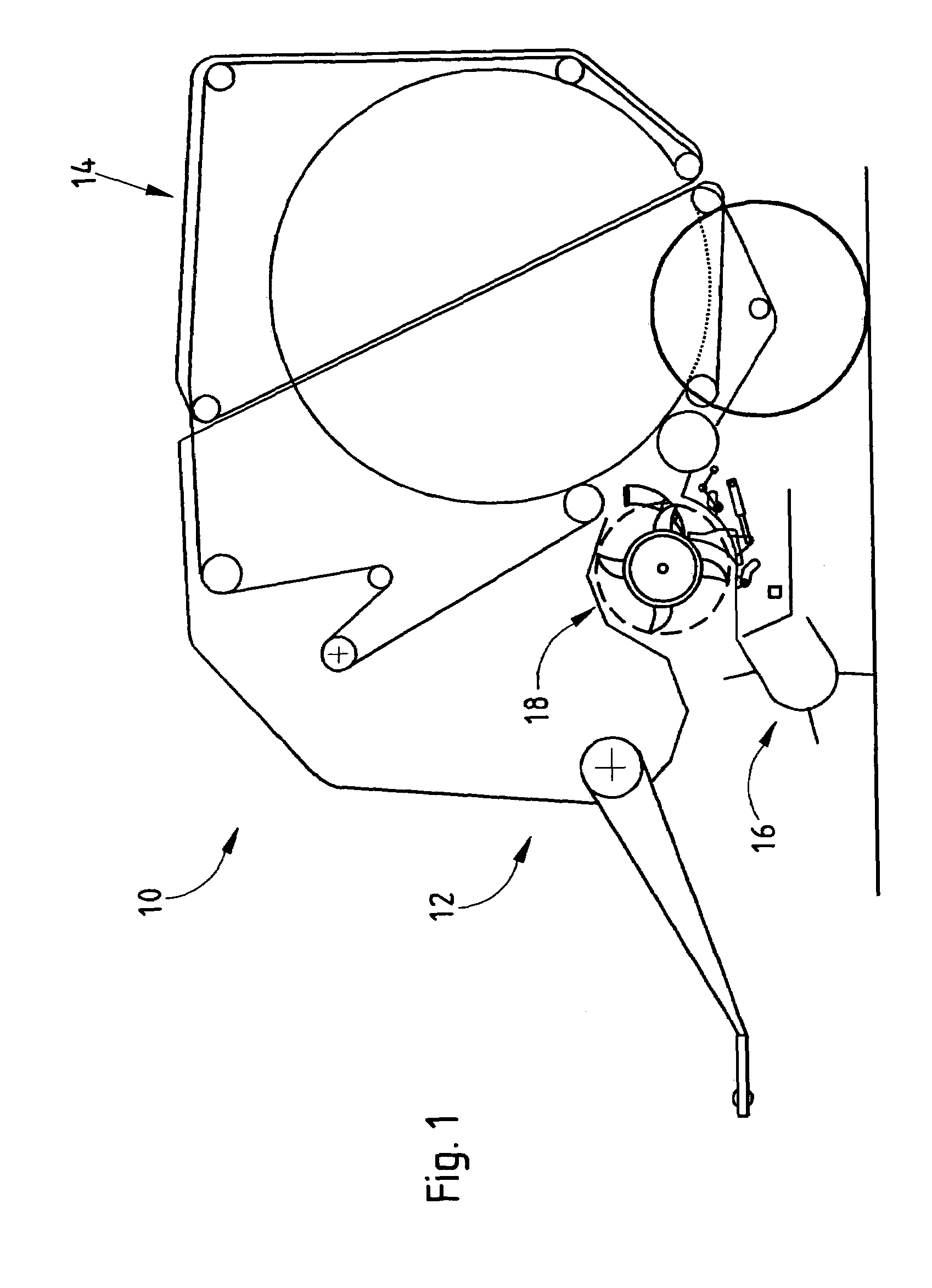
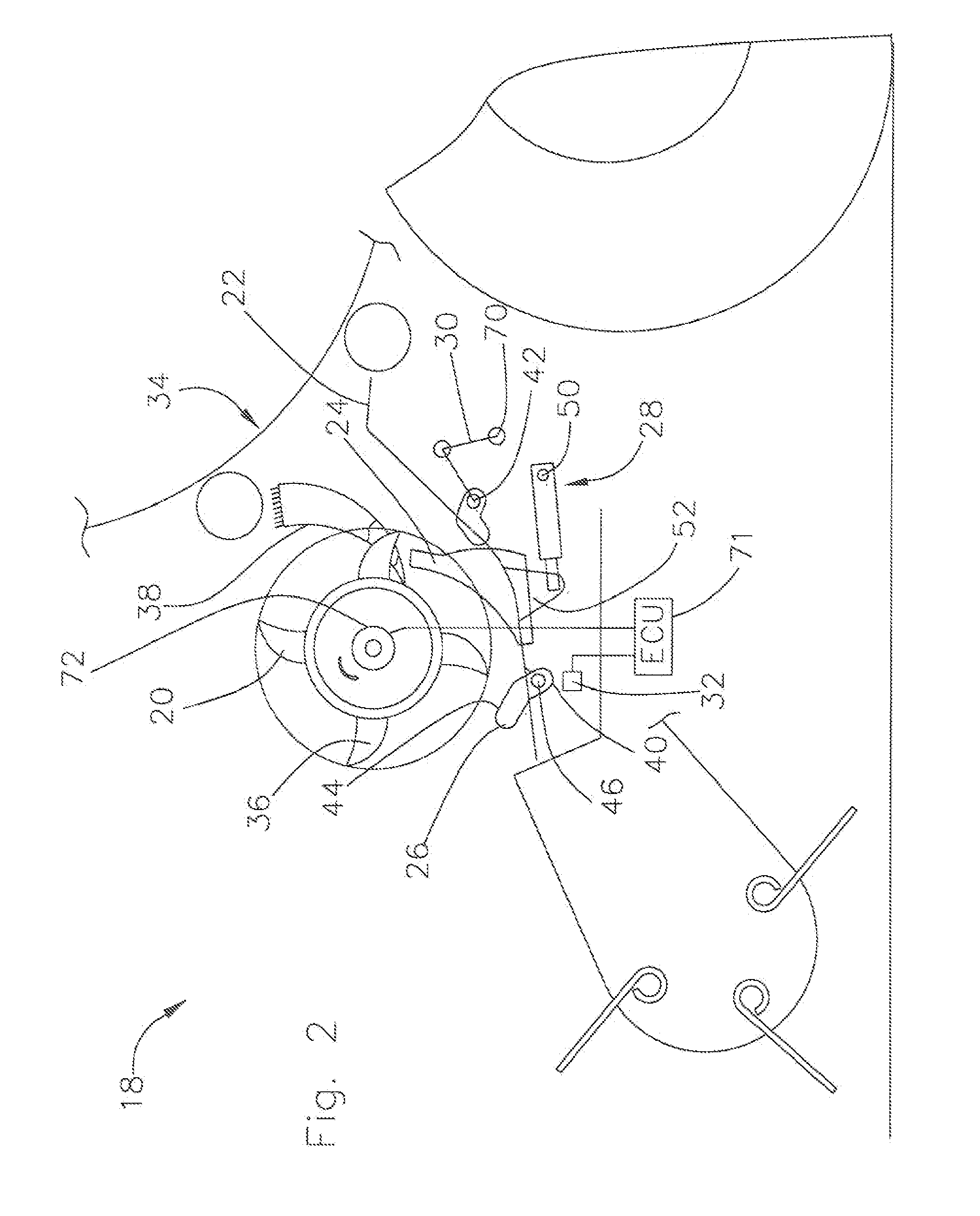
[0026]A round baler 10 according to FIG. 1 has a frame 12, a baling assembly 14, a pick-up 16 and an inventive crop processing device 18.

[0027]The round baler 10 is representative for any type of a crop collecting machine, like all types of round balers, large and small square balers, loading wagons, forage harvesters etc. useful in agriculture, forestry and in industry.

[0028]The frame 12 is composed of a chassis, tongue, axle, wheels, shielding, etc. and carries the baling assembly 14, the pick-up 16 and the crop processing device 18 for a movement over a field, a street etc. During the movement over a field, crop lying on the ground in a windrow is picked up and delivered to the baling assembly 14 for baling.

[0029]The baling assembly 14 is representative for other crop processing means and may be formed as a fixed, variable or mixed chamber pressing means, using belts, rolls, chains, or the like.

[0030]The pick-up 16 is as well of ordinary kind, known in the prior art and is locate...


PUM


Abstract

A crop processing device includes a rotor with crop engaging means, a sheet partly surrounding the rotor, whereas the sheet is circumferentially moveable with respect to the rotor, and a control providing resistance to circumferential movement of the sheet.

Description

FIELD OF THE INVENTION[0001]The present invention relates to a crop processing device having a rotor with crop engaging means and a sheet partly surrounding said rotor and the use of such a device.BACKGROUND OF THE INVENTION[0002]Prior patents DE 195 46 263 and DE 198 41 598 disclose cutting devices with a rotor and a bottom sheet, whereas the position of the bottom sheet is changeable as a function of the load created by the crop. The bottom sheet moves away from the rotor in an overload case and opens the throat thereby. It has been found, that instead of avoiding plugging such movement allows even more crop to enter, which increases the tendency to put the whole system on halt.[0003]The problem this invention is based on is seen in finding a crop processing device, which in an overload situation avoids plugging.SUMMARY OF THE INVENTION[0004]This problem is solved in an innovative way by means of the teaching of claim 1, whereas advantageous features further developing the inventi...

Claims


Application Information

Patent Timeline
Patent Type & Authority Patents(United States)
IPC IPC(8): A01F12/28A01D39/00A01D90/04A01F15/10A01F29/04
CPCA01D90/04A01F15/106A01F2015/107A01F2015/108
Inventor VIAUD, JEAN
Owner DEERE & CO
Why Eureka
Try Eureka